How Revs calculates track verges in the track section and track segment lists
The track in Revs is a thing of beauty, and a very large part of that beauty is down to the verge. Sometimes it's red-and-white, sometimes it's black-and-white, and sometimes it's thick and sometimes it's thin, but whatever it looks like, it's impressive just how immersive it is. That's because each and every part of the verge is simulated with the same accuracy as the rest of the game, and even though the track itself is just a mass of black, the accuracy of the colourful verges manages to make the whole track feel real.
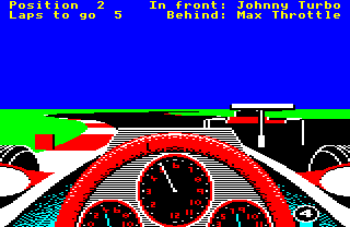
Here's a good example of a red-and-white verge, along the left edge of the track:
In this article we take a look at the maths behind the track verges, and how Revs calculates each one of those tiny verge marks as they whizz past your shoulder.
Overview of the calculation process
-----------------------------------
The main verge calculations are done in the GetVergeAndMarkers routine, which is called from the main driving loop. This routine does the following:
- Call GetSectionAngles to get pitch and yaw angles for the inner and outer track sections in the track section list and store the results in xVergeRight(Hi Lo), xVergeLeft(Hi Lo), yVergeRight and yVergeLeft.
- Call GetSegmentDetails and GetSegmentAngles to get the pitch and yaw angles for the segments (and the verge marks and corner markers) along the right side of the track and store the results in xVergeRight(Hi Lo), yVergeRight, xMarker(Hi Lo) and vergeDataRight.
- Do the same again to get the pitch and yaw angles for the left side of the track, storing the results in xVergeLeft(Hi Lo), yVergeLeft, xMarker(Hi Lo) and vergeDataLeft.
- Set the position of the horizon line according to the track sections and segments that we just processed.
In essence, GetVergeAndMarkers is all about populating the verge tables with the angles for each segment and section in the track view. As discussed in the deep dive on pitch and yaw angles, these angles feed directly into the screen coordinates, so this is effectively the first step in calculating what we need to draw for the track, and where.
The results of these calculations are stored in the track section list and the track segment list, which together make up the track verge buffer. The track verge buffer lets us cache the results, so we don't have to repeat complex calculations that we have already done. Note that the track verge buffer is distinct from the track segment buffer; the track verge buffer stores data about the track verges, while the track segment buffer stores data about segments. See the deep dive on data structures for the track calculations for more details about all these data structures, but all you need to know for now is that the results are stored to save recalculating.
Calculating the section angles
------------------------------
The GetSectionAngles routine is responsible for calculating the pitch and yaw angles of up to six track sections, which are then stored in the track section list. They are used when drawing the track in the DrawTrack routine. The GetSectionAngles routine does the following:
- If we have fetched a new track section since the last call, shuffle the track section list along by one, discarding the last section so we can insert the new section at the start. See the deep dive on data structures for the track calculations for more details of the shuffling process.
- Go through the track section list and apply the player's current spin to each valid entry (for both the right and left track section), skipping the entry pointed to by the sectionListPointer. Spin is applied by the SpinTrackSection routine, which applies spin from the spinYawAngle(Hi Lo) and spinPitchAngle variables, which are non-zero if the player's car is spinning on the track (following an accident or when losing grip, for example).
- Update the entry at sectionListPointer as follows:
- Calculate the track section number for this entry, relative to the front segment in the track segment buffer.
- Store the pitch and yaw angles for this section in the xVergeRight(Hi Lo) and yVergeRight tables, or the xVergeLeft(Hi Lo) and yVergeLeft tables (depending on which verge we are calculating).
This process updates the verge data for track sections in the list in an efficient way, by only recalculating one section's angles on each iteration of the main driving loop. The other sections in the list are updated by applying any spin (so if the car is spinning, the track spins appropriately), which is less accurate than a full projection, but does the job; these other sections are updated properly when it's their turn to be done.
The track section list contains up to six sections behind the front segment in the track segment buffer. They are stored in the track section list as follows, when we are facing forwards:
- Entry #5 in the list corresponds to the section behind the front segment
- Entry #4 in the list corresponds to two sections behind the front segment
- Entry #3 in the list corresponds to three sections behind the front segment
- Entry #2 in the list corresponds to four sections behind the front segment
- Entry #1 in the list corresponds to five sections behind the front segment
- Entry #0 in the list corresponds to six sections behind the front segment
The track section list contains the following for when we are facing backwards:
- Entry #5 in the list corresponds to the section containing the front segment
- Entry #4 in the list corresponds to the section behind the front segment
- Entry #3 in the list corresponds to two sections behind the front segment
- Entry #2 in the list corresponds to three sections behind the front segment
- Entry #1 in the list corresponds to four sections behind the front segment
- Entry #0 in the list corresponds to five sections behind the front segment
Note that entry #5 is the last in the list, and for most track sections, we only use the last few entries (e.g. for track section 0, the lower nibble of trackSectionData is 3, so we only use entries #3 to #5).
You can think of the track section list as a cache of section data, from the furthest section that we can see in front of us on the track (entry #5), working backwards towards the player. If the next set of track sections are quite bunched up, or we're cresting a hill and can see for a long way, then the higher the number of track sections that we need to cache in the track section list, to make sure we have cached all the sections we might see when looking along the track.
See the deep dive on data structures for the track calculations for more about the construction of the track section list and how it manages the shuffles and updates mentioned above.
Calculating the segment angles
------------------------------
The GetSegmentAngles routine is responsible for calculating the pitch and yaw angles of up to 16 track segment verges, to store in the track section list. They are used when drawing the track in the DrawTrack routine, and when calculating the positions of the corner markers.
This routine works through track segments, starting from distant segments and working backwards towards the player, calculating the verge data for each segment as we go, up to a maximum of 16 segments (which is the capacity of the track segment list). It also calculates the angles, distance and number of the segment within the track segment list that is closest to the player's car.
The yaw angle calculation calls the GetObjYawAngle routine, and uses the GetSegmentYawAngle routine to store the result in the track segment table. Similarly, the pitch angle is calculated by the GetObjPitchAngle.
If a segment is not visible on-screen, then part 2 of GetSegmentAngles stops processing any more segments. Because we are moving backwards through the segments towards the player, then once we stop being able to see segments, we don't need to cache any more for drawing on-screen, as we know the rest of the segments will also be behind the player. However, before we stop, we try to eke out as much accuracy out of the last (not visible) segment by trying to process a segment that's one-quarter of the size, just in case this smaller segment is visible, in which case we finish with something to show for the last visible segment (and if not, at least we tried).
If a segment is visible on-screen, then part 3 of GetSegmentAngles calls the GetVergeAndMarkers routine to get details for this segment's outer verge, as well as any corner markers and verge marks, before storing the angles in the track segment list and moving on to the next segment. See the deep dive on corner markers for details of the corner marker logic.
A final word about "moving on to the next segment". GetSegmentAngles doesn't fetch a contiguous sequence of segments. Instead, it fetches segments at the offsets given in the segmentStep table. The segment list contains 16 entries, with the first segment matching the front segment of the track segment buffer (i.e. 32 segments in front of the player). The next segment is 13 back from that, then the next is 6 back from that, then three back, and the rest of the segments step backwards by one segment. In other words, we fill the segment list like this:
- Step back 13 segments to 13 for segment list entry 1
- Step back 6 segments to 19 for segment list entry 2
- Step back 3 segments to 22 for segment list entry 3
- Step back 1 segment to 23 for segment list entry 4
- Step back 1 segment to 24 for segment list entry 5
- Step back 1 segment to 25 for segment list entry 6
- Step back 1 segment to 26 for segment list entry 7
- Step back 1 segment to 27 for segment list entry 8
- Step back 1 segment to 28 for segment list entry 9
- Step back 1 segment to 29 for segment list entry 10
- Step back 1 segment to 30 for segment list entry 11
- Step back 1 segment to 31 for segment list entry 12
- Step back 1 segment to 32 for segment list entry 13
- Step back 1 segment to 33 for segment list entry 14
- Step back 1 segment to 34 for segment list entry 15
- Step back 1 segment to 35 for segment list entry 16
Entry 32 in the track segment buffer is the player's car (as it is 32 segments behind the front segment), so the player's car is at entry 13 in the track segment list.
Let's look at the verge marks next.
Verge marks
-----------
The GetVergeAndMarkers routine calculates the colour and shape of the verge marks for a specific track segment (the verge marks are the black-and-white or red-and-white marks along the edge of the track). When a new segment is added to the track segment buffer by the GetTrackSegment routine, the segment's flags are calculated, based on the flags for the section containing that segment (these segment flags are then stored are stored in the segmentFlags table as part of the track segment buffer - see the deep dive on data structures for the track calculations for more about the buffer).
Let's see how the segment flags are built from the section flags. The section flags come from the second track section data block in the track data file (see the deep dive on the track data file format for details), and specifically from the trackSectionFlag byte, which contains the following flags that are relevant to the verge marks:
- Bit 1: Colour of left verge marks
- 0 = black-and-white verge marks
- 1 = red-and-white verge marks
- Bit 2: Colour of right verge marks
- 0 = black-and-white verge marks
- 1 = red-and-white verge marks
The GetVergeAndMarkers routine takes the flags for the current segment, and masks out the relevant bits, depending on whether we are processing the left or right verge. The byte is masked as follows:
  segmentFlags AND %00101101 for the right verge
                   %00110011 for the left verge
So when we are processing the right verge, we extract these flags while zeroing the rest:
- Bit 0 (section shape)
- Bit 2 (colour of right verge marks)
- Bit 3 (show right corner markers)
- Bit 5 (corner marker colours)
and when we are processing the left verge, we extract these flags while zeroing the rest:
- Bit 0 (section shape)
- Bit 1 (colour of left verge marks)
- Bit 4 (show left corner markers)
- Bit 5 (corner marker colours)
The routine then uses these flags to work out whether to show any corner markers as part of this segment (see the deep dive on corner markers for details), and what kind of verge mark the segment should have.
Each segment on the track corresponds to one verge mark, so when you see a red-and-white verge, you are effectively seeing each segment in turn, one red, then the next one white, then the next one red, and so on. As the GetVergeAndMarkers routine is called when adding just one segment to the buffer, we first need to work out the colour scheme of the section (i.e. red-and-white or black-and-white), and then the colour of the individual segment (black, white or red).
Part 1 of GetVergeAndMarkers sets the variable V to the verge colour scheme, using the lookup table at vergeColour. It does this by taking bits 0-2 of the masked segment flags from above, and putting them into Y, to give this range of possible values:
  Y = 0 = %000 = black right, black left, straight
  Y = 1 = %001 = black right, black left, curve
  Y = 2 = %010 = black right, red left,   straight
  Y = 3 = %011 = black right, red left,   curve
  Y = 4 = %100 = red right,   black left, straight
  Y = 5 = %101 = red right,   black left, curve
  Y = 6 = %110 = red right,   red left,   straight
  Y = 7 = %111 = red right,   red left,   curve
We then use Y as an index into the vergeColour table. When we are processing the right verge, we know bit 1 is clear, so the possible values of Y are as follows:
  Y = 0 = %000 = black right, black left, straight
  Y = 1 = %001 = black right, black left, curve
  Y = 4 = %100 = red right,   black left, straight
  Y = 5 = %101 = red right,   black left, curve
When we are processing the left verge, we know bit 2 is clear, so the possible values of Y are as follows:
  Y = 0 = %000 = black right, black left, straight
  Y = 1 = %001 = black right, black left, curve
  Y = 2 = %010 = black right, red left,   straight
  Y = 3 = %011 = black right, red left,   curve
So if Y = 0 or 1, then we know that the verge we are processing is black-and-white, otherwise it is red-and-white. Looking up the Y-th entry in the vergeColour table and storing it in V, we get the following:
  V = 0 when Y = 0 to 1 (black-and-white verge)
  V = 1 when Y = 2 to 7 (red-and-white verge)
So this gives us the verge type in V.
The final part of the GetVergeAndMarkers routine calculates the verge colour of the segment we are processing. It does this by simply checking whether the segment's offset within the segment coordinate tables is odd (in which case the segment is red or black, as specified in V) or even (in which case it is white), and then storing the colour in in the vergeDataRight or vergeDataLeft table, which form part of the track segment list. This is then used in the DrawTrack routine when drawing the track verges.
Verge width
-----------
The other important calculation is the verge width. We calculate the verge width as follows:
+/- scaleUp * 2 ^ (scaleDown - vergeScale)
where the sign is positive for the right verge and negative for the left verge, and higher values mean wider verges. In the above, scaleUp and scaleDown are the segment's scale factors, as set by the call to GetObjPitchAngle that we did in GetSegmentAngles before calling GetVergeAndMarkers, and vergeScale is the Y-th value from the vergeScale table, where Y is the index we calculated for the verge colour above.
The vergeScale factor is between 3 and 5, and scales the verge width differently for different track configurations, with larger values of vergeScale giving smaller verges (because vergeScale is subtracted in the above calculation). The values in the vergeScale table have the following effect:
- If both verges are black-and-white, then the verges are thin (vergeScale = 5), on both curved and straight sections
- If this is a curve and at least one of the verges is red-and-white, or we're on a straight and both verges are red-and-white, then the verges are medium thickness (vergeScale = 4)
- If this is a straight and only one of the verges is red-and-white, then the verges are thick (vergeScale = 3)
Once the verge width has been decided, we can calculate the coordinates for the outside edge of the track verge by adding the verge width to the track segment's verge coordinates (this will always move the track verge away from the centre of the track, as we set the sign of the verge width above). The result is stored in the track segment list, 16 bytes after the corresponding track segment entry, so indexes 6 to 21 contain the angles for the inner edge of the verge mark (i.e. the outer edge of the black part of the track), while indexes 22 to 37 contain the angles for the outer edge of the verge mark (i.e. where the verge mark meets the green grass).
The verge width is also used in the DrawTrack routine when drawing the verges into the screen buffer.