How Revs draws on-screen objects using nothing but vertical edges
When Revs draws on-screen objects such as cars and road signs, it does so in a way that you might not expect. Rather than drawing individual rectangles using horizontal lines, vertical lines and filled areas, absolutely everything gets drawn as a sequence of vertical edges. This might sound odd, but it fits in nicely with the way the screen buffer is stored in vertical strips in the dash data blocks, and it makes the process of drawing objects much more efficient than it would be with a horizontal approach. In this article, we take a detailed look at this edge-based drawing system.
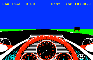
The best way to explain the drawing process is by example, so let's consider a familiar object: the black-and-white road sign by the side of the track when we start a practice lap of Silverstone. I'm talking about the sign on the right in this screenshot:

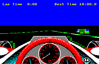
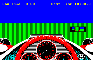
You can read more about this object in the deep dive on object definitions. When this screen is drawn in the screen buffer, it looks pretty different:

See the deep dive on drawing the track view for an explanation of the screen buffer. Here's the sign from the screen buffer with the dash data blocks superimposed, so you can see how the sign object fits into the dash data blocks that make up the screen buffer:

Again, see the deep dive on drawing the track view for an explanation of the dash data blocks and what the above images mean. For the purposes of this article, though, let's just focus in on the sign on the right, which looks like this in-game:

and like this in the screen buffer (along with a bit of the track verge):

and like this when superimposed over the dash data blocks:

Now, let's split the sign in the screen buffer into its constituent dash data blocks, like this (ignoring the all-black columns on either side, as they are empty):
| 1 | 2 | 3 | 4 | 5 |
 |
 |
 |
 |
 |
So to draw the sign by the side of the track, the game has to populate the screen buffer in the dash data blocks with these five different bits of content. Let's see how it does that.
Drawing edges
-------------
The sign object is made up of three parts, and the game draws the sign one object part at a time, in this order:
- Part 0 is the large rectangular part of the sign, with a black centre and white stripes down the sides
- Part 1 is the left leg, made up of a black edge on the left and a red fill, with no edge on the right
- Part 2 is the right leg, which is also made up of a black edge on the left and a red fill, with no edge on the right
Let's separate the contents of the sign in the screen buffer into these three parts, to give us the three sets of pixels that we need to draw in order to show the sign by the side of the track:
| 1 | 2 | 3 | 4 | 5 | |
| Part 0 |  |
 |
 |
 |
 |
| Part 1 |  |
 |
|||
| Part 2 |  |
 |
 |
For each of these object parts, the drawing routine does the following:
- Draw the block containing the left edge
- Draw the block containing the right edge
- Fill the object by drawing the blocks between the two edges, from right to left
- Fill the block to the right of the right edge, to ensure the background resumes to the right of the object
In the first two steps, if the right edge is in the same pixel byte as the left edge, we create a pixel byte containing both edges, and draw both edges into the screen buffer at the same time.
Note that in the context of the screen buffer, each dash data block is a four-pixel-wide column, so "drawing a block" means filling the relevant section of the dash data block with pixel bytes. Also note that &55 signifies black in the buffer, and &55 looks like a black-green-black-green striped pixel byte in the above, as that's what &55 would look like when poked directly into screen memory. The game converts this to black when drawing the contents of the screen buffer on-screen, but we're looking at the contents of the screen buffer here, not the screen, so we get the striped version.
Let's see this in action for part 0 of the sign. Here are the above steps in order, with each step drawing into one dash data block:
 | Block 1: Draw the left edge of the sign, with the white edge in the last pixel of the pixel byte, and the first three pixel bytes set to the existing background (blue for the top three pixel rows, green for the bottom three) |
 | Block 4: Draw the right edge of the sign, with the white edge in the second pixel of the pixel byte, the black fill colour of the sign in the first pixel, and then the final two pixels set to the existing background, just as for the left edge |
 | Block 3: Fill the inside of the object part in black, starting from the right, using a pixel byte of &55 as this represents four pixels in black (&55 displays as a black, green, black, green pixel byte when poked into the screen like this) |
 | Block 2: Continue filling the inside of the object part in black by moving to the left, again using a value of &55 |
 | Block 5: Fill to the right of the object using the existing background, which again is blue for the top three pixel rows and green for the bottom three rows |
For part 1 we have a slightly simpler process, as at this scale the leg isn't wide enough to contain any fill colour. That said, the right edge is an outside edge and this object part has the "draw outside edges in the fill colour" flag set, so the right edge is drawn in the fill colour (red), while the left edge is drawn in the edge colour (black). On top of this, we also have the left and right edges in the same pixel byte, so they are both drawn to the screen buffer in one go:
 | Block 2: Draw the left edge in the first pixel, the right edge in the second pixel, and the background colour in pixels three and four, drawing the combined result into the buffer in one go |
 | Block 3: Fill to the right of the object with the green colour of the background (note that this pixel byte gets overwritten by the left edge pixel byte of part 2) |
For part 2 it's a similar story, except the leg straddles two pixel bytes, and the first pixel byte for this leg overwrites the last pixel byte from the previous leg:
 | Block 3: Draw the left edge of the leg in the last pixel of the pixel byte, filling the first three pixels with the green background |
 | Block 4: Draw the right edge of the leg in the first pixel of the byte, filling the last three pixels with the green background |
 | Block 5: Fill to the right of the object with the green colour of the background |
Now we know what the edge-drawing process looks like, let's take a look at the code that actually does the drawing.
The object drawing routines
---------------------------
The main object drawing routine is DrawObject, which is responsible for drawing all the objects in Revs (so that's the road signs, the corner markers, the starting flag and all the different types of car). It does this by calling the DrawObjectEdges routine for each object that it needs to draw, so it calls DrawObjectEdges once when drawing a flag, and four times when drawing the four-object car, for example.
To draw an object, DrawObjectEdges runs through each of the object's parts in turn, and draws the part's vertical edges into the screen buffer as described above. The actual drawing is done by calling the DrawObjectEdge routine for each edge. This routine either draws the edge or, if the next edge is within the same byte, it prepares a pixel byte containing the current edge, ready for the next edge to be added in the next call to DrawObjectEdge. Once an edge has been drawn, DrawObjectEdge calls the FillInsideObject routine to fill the object (unless this is the first edge, in which case this step is skipped), and if we just drew the last edge, it calls the FillAfterObject routine to draw the existing background to the right of the object part.
For object parts that are simple rectangles, DrawObjectEdges calls DrawObjectEdge twice, once for the left edge and once for the right edge. For four-edge object parts, DrawObjectEdges calls DrawObjectEdge four times. The first call draws the left edge, and each subsequent call draws and fills up to the next edge, until the last call draws and fills up to the rightmost edge. FillAfterObject then takes over to restore the background to the right of the object, just as before.
Let's look at how the DrawObjectEdge routine breaks down, followed by the FillInsideObject and FillAfterObject routines.
DrawObjectEdge
--------------
The DrawObjectEdge routine is at the heart of the object-drawing process. It takes a large number of arguments, some of which are passed between subsequent calls to the routine. See the source code for a definitive list of arguments and return values.
- Set a number of variables that are required in the subsequent parts:
- leftOfEdge contains the fill colour of the object, or if the previous edge is within the same pixel byte and we are now drawing the next edge, it contains the pixel byte from the previous call, which contains the previous edge
- rightOfEdge contains the fill colour, or (if we need to draw this edge in the same pixel byte as the previous edge), it contains the pixel byte from the previous call
- edgePixel contains a four-pixel byte in the edge colour passed in bits 2-3 of colourData, which we will mask later to a single pixel
- thisEdge contains the pixel x-coordinate of the edge to draw
- blockNumber contains the dash data block number for the edge to draw (as each dash data block is four pixels wide)
- nextEdgeCoord and nextBlockNumber contain the pixel x-coordinate and dash data block number of the next edge, ready to be used in the next call to DrawObjectEdge
- Set (Q P) to the screen address of the dash data block containing the edge
- If this edge is off the right of the screen, jump to part 5 to check whether to fill the object up to the right edge of the screen
- Calculate the dash data block offset of the bottom line of the edge to draw
- Confirm that the top line is higher up the screen than the bottom line. If not and this is a left edge, stop drawing as there is nothing to draw; if not and this is a right or extra edge, jump to part 5 to move on to check for any filling we need to do, and move on to the next edge
- If bit 4 of the colour data is set and this is a left or right edge, check to see if it's an outside edge, and if so, set the edge colour to the fill colour so the edge merges into the object (so the edge is effectively hidden)
- Construct a single-pixel byte for the edge we want to draw in edgePixel, containing just the edge pixel in the correct colour
- Build a pixel byte in A containing the edge and fill colour, incorporating the previous edge if it's in the same pixel byte
- If the next edge is in the same byte, return from the subroutine with prevEdgeInByte != 0 so the next call can insert the next edge into the pixel byte
- Draw the edge by poking the edge and fill colours into the relevant dash data block, calling GetColour to fetch the current background colour of the pixel byte we are drawing the edge onto, so we can mask the background pixels into the correct side of the edge (i.e. to the left of the left edge, or the right of the right edge) and the fill colour on the inside of the object
- If the next edge in the object falls within the same pixel byte, then we do not poke the byte into screen memory, but instead store the pixel byte we have calculated so far, so the next call to DrawObjectEdge can pick it up, add the next edge into the correct place and poke the result into screen memory
- When poking the edge into screen memory, we simply fill the relevant dash data block, as sequential bytes populate columns on screen. The value &AA is used as a marker for the bottom of the edge to draw, with the marker being replaced by the original contents once the edge has been drawn
- If this is not the first edge, fill in the column after the edge we just drew, to reset the background colour to the right of the object ("after the object") by calling FillAfterObject
- If this is the start of a fill and there is at least one byte free after the edge before the next edge, fill the column to the left of the edge we just drew by calling FillInsideObject, also checking whether we need to fill to the right edge of the screen if the right edge is off-screen
- This part also contains a routine to work out whether the edge is off the right edge of the screen, and whether we should therefore be filling the object all the way up to the right edge
FillInsideObject
----------------
The drawing routine calls FillInsideObject when it finishes drawing any edge except the left edge (as we don't fill to the left of the left edge). This routine fills the object to the left of the edge we just drew, filling the object column by column (where each column corresponds to one dash data block).
- Calculate the address of the dash data block to the left of the edge into (Q P), so we can fill the object to the left of the edge, from right to left
- Calculate the address of the dash data block to the left of (Q P) and put it in (S R)
- Calculate the offset of the bottom of the object that we want to fill, using the fillDataOffset table to ensure that we drop down correctly if the dashboard is sloping down and left
- If we need to fill at least two columns, then we fill the two dash data blocks at (Q P) and (S R) concurrently; if we only need to fill one, then we only fill the column in (Q P)
- If there are more columns to fill, loop back to shift to the left by two dash data blocks, and repeat the process
FillAfterObject
---------------
After all the edges have been drawn in our object, the drawing routine calls FillAfterObject to reset the colour to the right of the object to the correct background. It does this by filling the column to the right of the object we just drew with the correct contents.
- Calculate the address of the dash data block to the right of the edge that we just drew
- Work down the screen (i.e. backwards through the dash data block in memory), and for each byte, check to see if it's a zero, and if so, replace it with the correct background colour (which is fetched by calling the GetColour routine)
The FillAfterObject routine is complicated somewhat by having a double use. Totally separate from the whole object-drawing process is the GetTyreDashEdge routine, which makes a copy of the contents of the screen buffer in the edge along the right side of the dashboard, as part of the process of fitting the track view around the dashboard - see the deep dive on drawing around the dashboard for details. The GetTyreDashEdge works by modifying the code in the FillAfterObject routine to copy the contents of an edge instead of filling it, so when reading the code, bear this in mind.
Also, the FillAfterObject, GetColour and GetTyreDashEdge routines from the original Acornsoft release of Revs were rewritten for the Superior Software release. The newer versions take up less memory and are considerably easier to follow, so I recommend you follow along with the Superior versions (which are called FillAfterObjectSup, GetColourSup and GetTyreDashEdgeSup).