Revs has a custom screen mode that conceals working code in a lush blue sky
Split-screen modes were all the rage in the BBC Micro games scene of 1984/5. It all started when Elite burst onto the market in September 1984, boasting graphics that were head-and-shoulders above the competition. I'll never forget opening Acorn User magazine and seeing this iconic screenshot, which still gives me the shivers decades later:
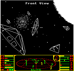
Sure, the 3D wireframe graphics are impressive enough on their own, but the stroke of genius is the way they are perfectly framed by a clever melding of high-resolution mode 4 graphics with low-resolution mode 5 graphics, enabling highly detailed spaceships in the monochrome space view, while the iconic 3D scanner makes the most of the chunkier four-colour dashboard. At the time, it completely blew people's minds; I know this, because I was one of them.
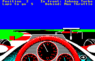
Revs followed soon after in the summer of 1985, this time using split-screen techniques to mix high-resolution text at the top of the screen with colourful but lower resolution graphics for the track and dashboard. It looks pretty good, even now; here's the screenshot from the back of the box:
As with Elite, Revs mixes mode 4 and mode 5, but that isn't the real story here, as that aspect is only used to squeeze decent amounts of text into the top two lines. Instead, Revs takes the interrupt-driven split-screen approach to a whole new level, splitting the screen into five different sections, each of them with a different palette. And buried in one of these sections - the section that contains the clear blue sky - is working game code, rendered invisible by the palette-switching techniques.
And this is all on top of a custom screen mode that takes up less RAM and enables an entire section of the game to run after the end of screen memory - that's off-screen and below the bottom of the dashboard. Elite has one page above screen memory that it uses for storing the Python ship blueprint, but Revs has a whopping five pages of code stuffed in there.
For more information about Elite, check out my deep dives into that game's split-screen mode and memory map, but to see how Revs takes this concept and blazes its own remarkable trail, stick around. Let's start with an overview of the custom screen mode, which lays the foundations for the magic that's hidden in the Revs split screen.
Features of the custom screen mode
----------------------------------
Before we go on, take a closer look at the Revs screenshot above, and see if there's anything obvious that screams "custom screen" to you. If you think it looks like a fairly normal BBC Micro screen mode, then join the club, as I had absolutely no idea just how special this screen mode was before I analysed it here, and I've looked at that screenshot plenty of times (heck, I recreated the above image by hand, pixel-by pixel from the box shot, so I've literally stared at it for hours without spotting its uniqueness). Geoff Crammond did a really good job here; the Revs screen hides its oddities very well, but there are a few clues if you know what to look for.
The first thing that leaps out is that this is a slightly smaller screen than we're used to on the BBC Micro - it isn't as tall, and has a more letterbox aspect. It is clearly using some kind of custom screen mode, and if you look more closely, there are more clues as to the nature of this custom screen.
For example, the text along the top of the screen is nice and compact, but the gear number on the gear stick at the bottom of the screen is really stretched in comparison. That's because these two sections of the screen use different screen modes with different resolutions: the top text uses mode 4, which fits 320 pixels across the width of the screen, while the gear stick uses mode 5, which only supports a width of 160 pixels.
And then there are the colours. Look carefully, and count how many of them there are. There's yellow text at the top (that's one) on a big blue sky (that's two). The track is black (three) with red and white edges (four and five), and lush green grass to the sides (that's six). Finally, the shading in the bottom corners of the dashboard is in cyan (seven). So, Revs uses a seven-colour screen mode, right?
Actually, it doesn't. If Revs were to use seven colours in one of the standard BBC Micro screen modes, it would have to use an eight-colour graphics mode, and there's only one of those: mode 2, which takes up a whopping 20K of RAM, with screen memory stretching from &3000 to &7FFF. But the Revs screen mode only stretches from &5A80 to &7AFF, which takes up 8320 bytes, or just over 8K. That's a massive difference that can't be explained by the smaller height of the Revs screen mode; there is something else going on here.
To find out what, let's take a deeper look at the custom screen mode.
The custom screen mode
----------------------
Before we get into the interrupt-driven mechanics of the split-screen mode, we first need to talk about the custom screen mode that Revs switches into at the start of each race. The SetCustomScreen routine is responsible for setting up this custom screen mode, which it does by reprogramming the registers in the 6845 CRTC chip, one of the chips that is responsible for creating the BBC Micro's screen display (the other chip being the Video ULA).
The register values that Revs sends to the 6845 for the custom screen mode can be found in the screenRegisters variable. Most of them have the same values as standard mode 5, but the custom mode has the following differences:
| Register | Details | Mode 5 | Revs |
|---|---|---|---|
| R2 | Horizontal sync position | 49 | 45 |
| R6 | Vertical displayed | 32 | 26 |
| R7 | Vertical sync position | 34 | 32 |
| R12, R13 | Screen memory start | &5800 | &5A80 |
In essence, the custom screen mode is a less tall version of mode 5, as R6 sets the number of character rows to 26 rather than 32 (making the screen 26 * 8 = 208 pixels high). We adjust the vertical and horizontal sync positions accordingly, and we also change the start of screen memory so it runs from &5A80 to &7AFF (as there are 26 character rows of 40 characters, with 8 bytes per character, giving 26 * 40 * 8 = 8320 bytes of screen memory, and &5A80 + 8320 = &7B00).
The final part of the mode-switching process is a call to OSBYTE 154, which sets the Video ULA's register 0 to %11000100 (the same value as for standard mode 5), and that's the end of the switching process. Importantly, because we are doing all this manually via the 6845 and Video ULA rather than using the operating system to switch to a standard screen mode, screen memory is not cleared, which is vital for Revs as by this point we've already unpacked the dashboard image into screen memory, and it would be a bit of a disaster to undo all our hard work (see the deep dive on the jigsaw puzzle binary for all the gory details of the unpacking process).
SetCustomScreen also takes the precaution of setting all four of the custom screen mode's colours to black, so when the screen mode actually changes, the player just sees a blank screen, rather than any of the content that's already present in screen memory (more of which later). But now let's take a look at how Revs takes the custom screen and splits it up into sections that mix screen modes and palettes to such great effect.
Interrupt-driven screen mode timers
-----------------------------------
As in Elite, Revs splits its screen mode up into sections by using interrupts and timers. Elite only splits its screen into two parts (the space view and the dashboard) while the Revs screen consists of five parts, but the theory behind the splitting process is the same.
Essentially, we use the 6522 User VIA chip to set a sequence of consecutive and continuous timers, where each timer counts down at a rate of 1 MHz - that's one million times a second - and triggers an interrupt when it runs down. We set up this sequence of timers carefully so that each of them counts down while a specific portion of the screen is being refreshed, which we can do as the 6845 is a CRTC controller - a Cathode Ray Tube Controller. On a period machine with a CRT monitor, there is literally a cathode ray inside the monitor that moves from left to right and up to down as it redraws the screen, faster than the eye can follow, so our timers match the progress of the ray as it works its way down the screen.
An interrupt is triggered when each of these timers runs down, and this in turn calls an interrupt handler routine - in other words, this routine is called every time the cathode ray reaches the end of a timed section of the screen. The handler routine checks which portion of the screen is about to be drawn next, and either changes the screen mode between modes 4 and 5, or changes the colour palette, all of which can be done by reprogramming the Video ULA.
In this way we can split the screen up into horizontal sections, each of which can have different resolutions and different colour schemes, and this allows us to squeeze all sorts of interesting features out of the screen mode. We'll talk more about the timers and interrupt routines later on, but first let's look at the screen split in more detail.
Splitting the screen five ways
------------------------------
Even if you know that the Revs screen is made up of five different parts, it isn't that obvious where the splits occur. Elite's screen split is pretty clear and easy to understand - there are two sections, one in monochrome, one in colour - but Revs is a lot more subtle, and splits the 208-pixel-high screen as follows:
| 0 |  | 18 pixels |
| 1 |  | 64 pixels |
| 2 |  | 19 pixels |
| 3 |  | 66 pixels |
| 4 |  | 41 pixels |
Each of those individual sections has either two or four colours (in high or low resolutions respectively), and the palette gets switched between sections so that more colours can be shown on-screen. Here are the details of each section:
| # | Base mode | Palette variable | Palette | Screen section |
|---|---|---|---|---|
| 0 | Mode 4 320 pixels 2 colours | paletteSection0 | 0 = blue 1 = yellow | Top two text lines |
| 1 | Mode 5 160 pixels 4 colours | - | 0 = blue 1 = blue 2 = blue 3 = blue | Blue sky |
| 2 | Mode 5 160 pixels 4 colours | paletteSection2 | 0 = black 1 = blue 2 = white 3 = green | Horizon and rear wings |
| 3 | Mode 5 160 pixels 4 colours | paletteSection3 | 0 = black 1 = red 2 = white 3 = green | Track |
| 4 | Mode 5 160 pixels 4 colours | paletteSection4 | 0 = black 1 = red 2 = white 3 = cyan | Dashboard |
If you look at the different sections above, you can see that the colour palettes in the table match what's shown on-screen. For example, the horizon portion in section 2 uses black, blue, white and green, so it can draw sky, grass and the rear wing (the latter being in black-and-white). The track portion in section 3 changes the blue of colour 1 into red, to give black, red, white and green, so it can draw grass, track, edge markers and cars (we don't need blue any more as the track doesn't contain any sky). And then in the final section 4, we no longer need to draw grass, so we can swap the green of colour 3 to cyan, to use as shading in the dashboard design.
This is pretty neat, but there's an even more impressive trick. All these palette transitions are cleverly designed to prevent screen artifacts, which can occur if the CPU is busy servicing a different interrupt when a timer runs down. You see these artifacts all the time in Elite, where the border between the space view and dashboard can sometimes be a bit flickery. Revs, though, is rock-solid, so much so that it really isn't obvious that there's a split screen here in the first place.
This is because the palette changes are designed to cope with delays in the switching. The first switch waits until we're past the text, and then switches the screen mode in a part of screen memory that just contains zeroes, so it always switches from a blue mode 4 screen to a blue mode 5 screen (you can see this in the image in the next section - it's the blue gap between the text at the top of the screen and the hidden code). The switch to the horizon section happens way before any rear wings might appear, and the switch to the track happens after we have finished with the blue of the sky, but quite a few scan lines before any red might appear on the distant part of the track. Finally, the switch to cyan for the dashboard happens way before we need it, so again we never see any artifacts. It's really slick stuff.
But the blue sky - that's the most interesting part. Let's see why.
Hiding in plain sight
---------------------
As you have probably worked out by now, the blue sky is anything but. In fact, it's crammed with running code and data, which you can see in the following screenshot, showing what the game looks like if the palette switch between sections 0 and 1 is disabled:
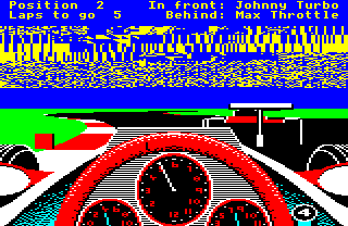
So what's in this garbled mess of code? Well, there are two rows of text at the top of the screen, each of which is eight pixels high, but these are spaced out by an extra pixel compared to the normal on-screen character rows (there's an extra one-pixel gap above the top text row and another extra one-pixel gap between the text rows). So the two lines of text take up 18 pixel lines at the top of the screen, which equates to two on-screen character rows of eight pixels each, plus another two pixels for the gaps. Just to be sure, the game blanks out the top three character rows as part of the loading process, so we know that the top 24 pixel rows start out blank, giving us six rows of blank pixels just below the second text line.
(To put this in terms of screen addresses, the screen starts at &5A80 and each character row takes up &140 bytes, so the top three character rows take us up to &5A80 + 3 * &140 = &5E40. This memory block is zeroed by the loader's unpacking process - see the deep dive on the jigsaw puzzle binary for details.)
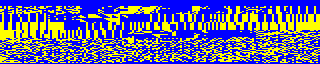
Section 1 starts on pixel line 19 of the screen, right after the second line of text, so we know that the first six pixel lines of section 1 are zeroed. This is where the mode switches from mode 4 to mode 5, so these six pixel lines ensure we don't get any screen artifacts, as mentioned in the previous section. This is what section 1 looks like with the code visible, where you can clearly see the gap at the top:
From &5E40 to &66FF, things are rather different. This memory isn't empty, but contains various data blocks and routines that happily continue to run in screen memory. There are lots of variables from &5E40 to &6300, at which point we switch to code, starting with the GetTextInput routine, followed by routines like SetDriverSpeed and the main game loop at MainLoop, until we cap it off with the likes of AddRacePoints, GetDriverName and DrawCars.
So there's a lot packed into the sky, but because the palette shows all four colours as blue, we can't see any of it, we just see a blue sky stretching all the way to the horizon. The code ends just before the end of section 1, ready for the palette switch to the horizon section.
It's a really clever way of squeezing more code and content into memory without compromising the size of the game screen. The blue sky might be fairly large, but when you're concentrating on the horizon in a battle to overtake Johnny Turbo, snatching glances in the wing mirror to keep Max Throttle in his place... well, you're probably a bit too busy to stop and wonder that the sky is full of code, busily beavering away under the bonnet.
For now, let's take a deeper look at how the code manages this splitting process, using timers to drive the entire process.
Initialising the timers
-----------------------
As mentioned above, we use the 6522 User VIA's timer to trigger the interrupt handler in ScreenHandler at the correct points in the screen refresh, so we can do our mode and palette switching. (The 6522 System VIA's timer is also set in these routines, but this isn't related to the split screen, so I will ignore it here.) Here are the specific details of what happens, and when.
When we first switch into the custom screen mode in the SetCustomScreen routine, by reprogramming the 6845 and Video ULA as described above, we then wait for the next vertical sync. This ensures that all the subsequent timers will fire at the correct times, and therefore at the correct points during the screen redraw. We then set up the first timer as follows:
- Configure continuous interrupts for the User VIA timer 1, so the timer restarts straight away after it runs down
- Enable the Timer1 interrupt, so our interrupt handler gets called when timer 1 runs down
- Start timer 1 counting down, by setting T1C-L = &D4 and T1C-H = &11, so it starts counting down from &11D4 (4564)
- Latch new figures into the timer, by setting T1L-L = &1E and T1L-H = &4E to give &4E1E (19998), so when the timer finishes the current countdown, it instantly starts again from this new figure
This is fairly gnarly, but essentially we're setting up the User VIA timer 1 so that it keep counting continuously, calls our routine each time it runs down, starts counting from &11D4, and then starts counting down from &4E1E once the first countdown is done. This sets up the timers so the interrupt handler can take over from here.
The final thing that SetCustomScreen does is to point the interrupt vector in IRQ1V to ScreenHandler, so from now on, when timers run down, the system calls the ScreenHandler routine. Let's take a look at this routine next.
Drawing the split screen
------------------------
When it's called, the interrupt handler at ScreenHandler does a quick check to see whether it is being called because of User VIA timer 1 running down, and if it's being called for any other reason, it simply passes control to the original interrupt handler, so it can deal with the interrupt instead. If, however, the User VIA's timer 1 did just run down, our handler routine swings into action.
First, it clears the interrupt so it's ready to be triggered again when the next timer runs down. Then it checks the value of the screenSection variable, which keeps track of which of the five screen sections we have now reached, and depending on this value, it does one of the following:
- If screenSection = 0, we are about to draw the top two lines of text, so we:
- Set the Video ULA to screen mode 4
- Set the palette using the values in the paletteSection0 variable:
- 0 = blue
- 1 = yellow
- Latch in a new User VIA timer 1 value of &0FC4 (4036), which will start counting when section 1 starts, and create an interrupt when section 2 starts
- Increment screenSection to 1, so when the current timer runs down, the handler will be called with screenSection = 1
- Return from the interrupt handler
- If screenSection = 1, we are about to draw the sky, so we:
- Set the Video ULA to screen mode 5
- Set the palette to the following:
- 0 = blue
- 1 = blue
- 2 = blue
- 3 = blue
- Set screenTimer2 = &153C - screenTimer1
- Latch in a new User VIA timer 1 value of screenTimer1, which will start counting when section 2 starts, and create an interrupt when section 3 starts
- Increment screenSection to 2, so when the current timer runs down, the handler will be called with screenSection = 2
- Return from the interrupt handler
- If screenSection = 2, we are about to draw the horizon and any rear wings that might be visible, so we:
- Set the palette using the values in the paletteSection2 variable:
- 0 = black
- 1 = blue
- 2 = white
- 3 = green
- Latch in a new User VIA timer 1 value of screenTimer2, which will start counting when section 3 starts, and create an interrupt when section 4 starts
- Increment screenSection to 3, so when the current timer runs down, the handler will be called with screenSection = 3
- Return from the interrupt handler
- Set the palette using the values in the paletteSection2 variable:
- If screenSection = 3, we are about to draw the track, so we:
- Update the palette using the values in the paletteSection3 variable:
- 1 = red
- Latch in a new User VIA timer 1 value of &1E00 (7680), which will start counting when section 4 starts, and create an interrupt when section 0 starts
- Increment screenSection to 4, so when the current timer runs down, the handler will be called with screenSection = 4
- Return from the interrupt handler
- Update the palette using the values in the paletteSection3 variable:
- If screenSection = 4, we are about to draw the dashboard, so we:
- Update the palette using the values in the paletteSection4 variable:
- 3 = cyan
- Set screenSection = -1
- Call the AnimateTyres routine to animate the tyres, if we are moving
- Latch in a new User VIA timer 1 value of &0B16 (2838), which will start counting when section 0 starts, and create an interrupt when section 1 starts
- Increment screenSection to 0, so when the current timer runs down, the handler will be called with screenSection = 0
- Return from the interrupt handler
- Update the palette using the values in the paletteSection4 variable:
Notice the way that the timers are set and when they start counting. When we set the value of timer 1 in the handler, we latch the value in, so it doesn't start counting right away, but instead waits for the current counter to finish before moving on to the new value. This means that if we are in the handler with screenSection = n, and we latch a value in timer 1, then the handler will be called with screenSection = n + 1 when the current timer runs down, and it will be called with screenSection = n + 2 when the timer that we just set runs down.
This pipelining of timer countdowns ensures that the whole process continues like clockwork and without missing a beat, as the timers continue their unstoppable counting even if the CPU gets battered with interrupts. A busy CPU might mean that our handler gets called slightly late, but it won't affect the regularity of the interrupts, which keep on going in the background, literally like clockwork.
For completeness, the handler can also be called with screenSection set to -2 or -1. When the custom screen is first set up by SetCustomScreen, the palette is set to all-black (so there is nothing shown on screen at all) and screenSection is set to -2, which makes the interrupt handler do nothing, so the palette stays all-black; we do this so that we can draw the track and cars before revealing the screen for the first time, which is done in the main driving loop by incrementing screenSection to -1. When screenSection is -1, the interrupt handler does the same as for screenSection = 0, but we don't change the screen mode or set the palette, we just latch &0FC4 into timer 1 and set screenSection to 1. This initialisation process ensures a smooth appearance for the custom screen when it's first switched on.
The resulting chain of timers looks like this, where timer1 is the 16-bit value of screenTimer1, and the numbers on the right show the start number of the timer countdown that happens while each section is being drawn (so section 0 is drawn while the timer counts from &0B16 to zero, for example):
| 0 | | &0B16 |
| 1 | | &0FC4 |
| 2 | | timer1 |
| 3 | | &153C - timer1 |
| 4 | | &1E00 |
Looking at the above, you can see that together, sections 2 and 3 always take up &153C timer ticks, but the point at which section 2 switches to section 3 - i.e. the point where the horizon palette switches to the track palette - is determined by the value of screenTimer1, which specifies the amount of time spent on section 2. The value of screenTimer1 is set in the MoveHorizon routine, where it's assigned a value of &04D8 plus or minus a calculated value that depends on the height of the horizon in horizonLine.
The calculated value is in the range -704 to 1152, so timer1 is in the range &0218 (when the car is in a dip) to &0958 (when the car is cresting a hill) - in other words, when we are in a dip, the horizon moves up the screen, and when we are on top of a hill, the horizon moves down the screen, as expected. Note that this only moves the point at which the palette changes; the horizon itself is also drawn at the relevant height, but that is done by the drawing routines, rather than the custom screen handler.
Adding up all the timers in the above, and adding 2 ticks to cater for the latching process, we get the following total time for drawing the whole screen:
    &0B16 + 2 + &0FC4 + 2 + timer1 + 2 + &153C - timer1 + 2 + &1E00 + 2

  = &0B16 + 2 + &0FC4 + 2 + 2 + &153C + 2 + &1E00 + 2

  = 2838 + 2 + 4036 + 2 + 2 + 5436 + 2 + 7680 + 2

  = 20,000
So it takes exactly 20,000 ticks of the 1 MHz counter to draw the screen, or 0.02 of a second (as the 1 MHz counter ticks one million times a second). This means we complete 50 cycles through all the counters in one second, which ties in nicely with the screen's refresh rate of 50Hz.
And that's how the split screen works in Revs. So the next time you're driving around Silverstone, take a moment to look up into the sky. You might not be able to see it, but up there amongst the clouds are wisps of Geoff Crammond's exceedingly clever code, hiding in plain sight.