What the little markers by the trackside tell us about driving around corners
Corner markers are small flags that sit by the track verge. They can appear on straight track sections, where three consecutive markers (white, white, red) indicate that we're getting towards the end of the section, and they can appear on curved track sections, in which case a single red marker indicates the halfway point around the corner. They can appear on either side of the track - or, technically, on both sides at once, though Silverstone does not make use of this feature.
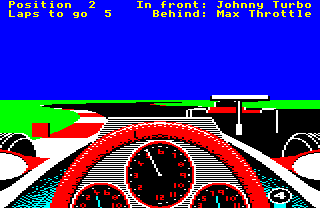
You can see a corner marker on the left in the following picture; this is a single red marker that indicates the halfway point through the left curve that the cars are on.
Let's see how corner markers are implemented.
Marker colours
--------------
The logic behind the corner markers is spread out across a number of places in the code, but the key part is in the GetTrackSegment routine. When a new segment is added to the track segment buffer by this routine, the segment's flags are calculated. They are based on the flags for the section containing that segment, but with changes that are specific to that particular segment. These segment flags are then stored are stored in the segmentFlags table as part of the track segment buffer - see the deep dive on data structures for the track calculations for more about the buffer.
Let's see how the segment flags are built from the section flags. The section flags come from the second track section data block in the track data file (see the deep dive on the track data file format for details), and specifically from the trackSectionFlag byte, which contains the following flags that are relevant to corner markers:
- Bit 3: Show corner markers on right
- 0 = do not show corner markers to the right of the track
- 1 = show corner markers to the right of the track
- Bit 4: Show corner markers on left
- 0 = do not show corner markers to the left of the track
- 1 = show corner markers to the left of the track
- Bit 5: Corner marker colours
- 0 = show all corner markers in white
- 1 = show corner markers in red or white, as appropriate
Part 2 of the GetTrackSegment routine decides whether or not the segment being added to the track segment buffer should have a corner marker associated with it, and alters the segment flags for that segment accordingly. For example, if the segment does not have a corner marker, then bits 3 and 4 in that segment's flags will get cleared. Or if the segment has a marker but it should be white, which is the case for the first two markers at the end of each straight segment, then bit 5 will get cleared.
The logic is as follows:
- For straight sections, a segment potentially gets a corner marker if its position within the section is exactly 7, 14 or 21 segments before the end of the section, with the markers at 21 and 14 segments being white (bit 5 clear), and the marker at 7 segments inheriting the section's bit 5 setting (so it's red if bit 5 is set, white otherwise)
- For curved sections, the segment that is halfway through the curve potentially gets a corner marker (i.e. the segment whose number is half the section's trackSectionSize value), with the marker colour determined by bit 5 (red if set, white otherwise)
The reason that segments only potentially get corner markers is that the section flags override everything. So a section whose bits 3 and 4 are clear in their trackSectionFlag in the track data file will never show any corner markers at all, while a section with bit 3 clear and bit 4 set will show one or more markers on the left side of the track, as determined by the section shape. Bit 5, meanwhile, controls the colour of the last marker (for straights) or the only marker (for curves); if it's clear, all markers in the section are white, but if it's set, then the last marker (for straights) or the only marker (for curves) is shown in red. The first two markers in a straight are always shown in white.
That covers the colour and configuration of the corner markers, so let's finish off by looking at the coordinates of these markers.
Marker coordinates
------------------
Unlike verge coordinates, marker coordinates are not stored in the track segment buffer; the only marker-specific data in the track segment buffer are the relevant segment flags. Instead, there is a marker buffer that stores the details of up to three corner markers. You can configure six markers to appear at once, by setting both bits 3 and 4 for a straight section in the section's trackSectionFlag, but only three of them will appear at any one time; the Silverstone track does not set markers to appear on both sides of the track at once, so this never an issue in the released game.
To support these markers, there's a dedicated set of tables and variables for storing the details of up to three of them, as follows:
- markersToDraw contains the number of markers that we need to draw on-screen (0 to 3)
- The markerListIndex table contains the index of each marker's segment in the track segment list (one entry per marker)
- The markerData table contains the masked segment flags for each marker (one entry per marker)
- The (xMarkerHi xMarkerLo) tables contain the verge width where the marker should be shown (one 16-bit entry per marker)
The GetVergeAndMarkers routine is responsible for populating the above. It does during the verge calculations described in the deep dive on the track verges. The first two bits of data are obvious enough, but let's take a quick look at the other two, markerData and (xMarkerHi xMarkerLo).
There are more details about the flags that we store in markerData in the aforementioned deep dive on the track verges, but to summarise, the masked segment flags in markerData contain the following data when we are processing the right verge:
- Bit 0 (section shape)
- Bit 2 (colour of right verge marks)
- Bit 3 (show right corner markers)
- Bit 5 (corner marker colours)
And they contain these bits of data when we are processing the left verge:
- Bit 0 (section shape)
- Bit 1 (colour of left verge marks)
- Bit 4 (show left corner markers)
- Bit 5 (corner marker colours)
Three of these are relevant to the corner marker calculations (the exception being the verge mark colour flags). See the deep dive on the track data file format for more about the track section and segment flags.
The last bit of data is (xMarkerHi xMarkerLo), which contains the verge width, for use when calculating the marker coordinates (see the deep dive on the track verges for details of the calculations behind this value). For straight sections, the verge width is stored unaltered in (xMarkerHi xMarkerLo), but for curved sections, the verge width is halved before being stored in (xMarkerHi xMarkerLo). The value in (xMarkerHi xMarkerLo) is doubled when it is read in the DrawCornerMarkers routine, so this means that the single corner markers in the middle of curved sections appear right on the edge of the verge, while the markers for straight sections have a gap between them and the verge, with that gap being equal to the verge width.
When drawing the corner markers, the DrawCornerMarkers routine sets the correct palette for the marker, depending on the marker's markerData entry, so the marker is drawn in red or white as required. It then takes the coordinates of the associated segment (which are stored at index markerListIndex in the track segment list), and adds the value in (xMarkerHi xMarkerLo), doubled, to get the x-coordinate of the marker. It then gets the y-coordinate from the segment's yVergeRight value in the track segment buffer, and calls DrawObject to draw an object of type 6.