How Revs uses its screen buffer to produce smooth and speedy graphics
As with pretty much every Geoff Crammond game, Revs has beautifully smooth graphics. There are none of Elite's famously flickery space scenes here; the cars in Revs squeal around the corners without even a hint of shimmer, and even amongst the engine roars of a closely packed starting grid, or in the inevitable spin-out on the chicane (yet again!), things don't slow down a bit. Revs clearly has some sophisticated drawing technology under the hood.
Even in his previous game, Aviator, the graphics were ground-breaking for their time. That game owes its flicker-free cockpit view to palette switching and colour cycling, which you can read all about in this deep dive. The trade-off for this smoothness is a monochrome game that uses all the memory of a four-colour screen mode, but not only is Revs gloriously colourful and just as smooth, it needs all the memory it can get for its sophisticated simulation, so colour cycling simply isn't an option.
Luckily, the part of the screen that shows the track, cars, road signs and so on - the "track view" - fits into a relatively thin strip across the centre of the screen, so it's possible to achieve smooth graphics without resorting to colour cycling. Instead, Revs uses a screen buffer for composing the track view, and then it draws the contents of the buffer on-screen using highly optimised drawing routines that manage to update the track view quickly enough to avoid any flicker.
Let's take a deeper look at what's involved.
The screen buffer
-----------------
Spread throughout the Revs codebase are 40 memory blocks - the "dash data blocks" - which Revs uses as a screen buffer when we're on the track. The mechanics of these blocks are pretty complicated, and are covered in detail in the deep dives on the jigsaw puzzle binary and drawing around the dashboard. For the purposes of this deep dive, all you need to know is that the 40 dash data blocks are used as a screen buffer for the contents of the track view, which breaks down like this:

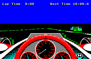
Each of the green strips is one of the dash data blocks, and together they form a screen buffer that covers the whole track view - so that's the lower part of the sky, the horizon, the grass verges, the track verges, the track itself, the cars, the road signs, corner markers and starting flags. Here's a typical screenshot, for comparison:

To draw something on-screen, we draw into the relevant part of the screen buffer (i.e. into the relevant dash data block), and then the drawing routines take the contents of the screen buffer and update the screen.
The key to understanding the screen buffer lies in the routine that copies the screen buffer to the screen. This forms a core part of the Revs graphics engine, so let's take a look at this next.
The DRAW_BYTE macro
-------------------
The most important element of the graphics engine is the DRAW_BYTE macro. This tiny bit of highly optimised code is responsible for copying one byte - i.e. four pixels - from the screen buffer, drawing it on-screen and resetting the screen buffer as it does so. Each dash data block is one byte wide (so the green columns in the above picture are each one byte wide), so this macro draws a one-pixel-high and one-column-wide line from one of those green columns.
Here's the code from the DRAW_BYTE macro:
   LDY dashData+&80*I%,X
   BEQ P%+10
   LDA #0
   STA dashData+&80*I%,X
   LDA zeroIfYIs55,Y
   LDY #LO(8*I%)
   STA (P),Y
This code copies a single pixel byte from dash data block I% into screen memory - in other words, into column I% in the above picture. The offset of the byte within the dash data block is given in X (which we set up before running the macro's code), and the 16-bit address in P points to the screen address of the left end of the pixel line on which we want to draw. For more details on exactly how each instruction works, see the annotated source code.
Each DRAW_BYTE macro instance copies one byte from the screen buffer into screen memory, but it isn't a direct copy. Instead, this tiny bit of code does the following:
- If the dash data byte is zero, then the current value of A is stored in screen memory (i.e. the value that was stored by the previous DRAW_BYTE).
- If the dash data byte is non-zero, then this is stored in A and screen memory, unless it is &55, in which a zero is stored in A and screen memory.
- As it is copied, the source dash data byte is zeroed, so the macro effectively moves a byte from the screen buffer into screen memory, clearing it in the process.
We'll take a look at what this all means in a second, but before we do, take a moment to appreciate just how compact this code is. All of the logic above is implemented in just seven instructions, which is impressive. In particular, look at the second step, which is implemented by the zeroIfYIs55 table. This is a table of 256 bytes, going from 0 to 255, so that's a 0 in byte #0, a 1 in byte #1 and so on up to a 255 in byte #255... except for byte #&55, which contains a zero. This means that the LDA zeroIfYIs55,Y instruction sets A to the value in Y, unless Y is &55, in which case it sets A to 0.
So why the lookup table? It's to make things as fast as possible. This whole macro has been optimised for speed at the expense of memory; having a 256-byte table just to implement this one bit of logic is pretty memory-intensive, but DRAW_BYTE is run for every single byte in the track view, every time the track view is updated, which means that every single cycle counts. A more typical conditional approach to this logic might look like this:
   TYA
   CMP #&55
   BNE P%+4
   LDA #0
This takes seven CPU cycles, while the LDA zeroIfYIs55,Y instruction takes just four cycles, which is almost half the speed of the conditional approach. These small differences really add up when you're trying to build a super-fast graphics engine out of repeated elements.
The speed optimisations extend to the entire line-drawing routine, which is implemented in DrawTrackLine. After setting up the various variables used in the macro, DrawTrackLine falls through into the DrawTrackBytes routine, which consists of 40 sequential instances of the DRAW_BYTE macro. There is no loop here - instead, the loop is unrolled at the expense of using yet more memory, all to give a faster screen update routine. Each macro instance draws one pixel byte into screen memory, so the full sequence of macros, from DRAW_BYTE 0 through DRAW_BYTE 39, draws a one-pixel high line across the full width of the screen.
So DRAW_BYTE is the key to understanding the screen buffer, but what does the above logic mean? Let's take a closer look.
Fast filling with the screen buffer
-----------------------------------
To recap, the DRAW_BYTE macro copies data from the screen buffer into screen memory, applying the following logic as it does so:
- A zero in the screen buffer means: store the value from the previous pixel byte in screen memory.
- A &55 in the screen buffer means: store a zero in screen memory.
- All other values in the screen buffer mean: copy the value from the screen buffer into screen memory without making any changes.
Not only is the copying code optimised for speed, but the logic that it implements has a profound effect on how we draw things in the screen buffer in the first place. Specifically, the steps above enable the graphics engine to implement filled graphics without needing any fill routines, and without any speed penalties. It's genius.
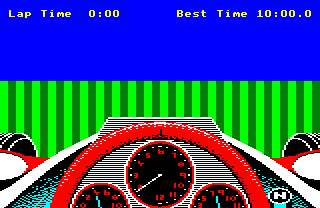
Let's look at an example of filled graphics in action. Consider the view that we get at the start of each practice lap:

This looks like a scene where you would need to do a lot of filling. In particular there's the grass and the sky, which are all surely colour-filled in some way, but it turns out that this excellent example of beautiful filled graphics doesn't actually contain any fills.
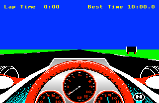
To see this, we can tweak the DRAW_BYTE macro to remove the above logic, so instead of displaying the normal track view, it simply copies the contents of the screen buffer directly to the screen without making any changes. If we do this, then we get the following:

So it turns out that there's not actually much in the screen buffer - just a few pixels along the edges of the track, a few more around the dashboard, and then a block of pixels for the road sign. This is because the screen buffer only needs to contain edge data, and the DRAW_BYTE macro converts these edges into filled objects.
The key to understanding why this works is in the first bullet point above. If we have a zero in the screen buffer, then DRAW_BYTE will poke the value from the previous DRAW_BYTE into screen memory... and if that was a zero, then that will have used the previous value to that one, and so on. As we draw lines from left to right each time, this means that if we have a non-zero byte - say, a pixel byte for four green pixels - then if the bytes to the right of that green pixel byte are zeroes in the screen buffer, then they will be converted into green pixel bytes by DRAW_BYTE, until we bump into another non-zero pixel to the right, at which point the current pixel byte will change to the new one.
That's also why we use &55 to denote black. A value of zero in the screen buffer means "keep using the colour from the left", so we repurpose &55 to represent black. This is why the DRAW_BYTE macro converts screen buffer values of &55 to zero, so we can switch the colour to black without using zero in the buffer. That's what the black-and-green bytes mean, such as those to the right of the dashboard - they mean "switch to black".
That's also why DRAW_BYTE zeroes each byte in the screen buffer as it draws the screen, so it leaves a blank canvas for the next frame in the animation. There's also one more table, called backgroundColour, that stores the colour of the pixel byte to the left of the screen for each track line - the background colour, if you like - so we know which colour to start with when drawing each line. Given this, we can rely on the logic in DRAW_BYTE to flood-fill all the blank areas with the correct colour, i.e. all those areas that are shown in black in the screen buffer image above.
So to draw a horizontal line on the screen, we need only draw the leftmost pixel byte, and if we leave the subsequent bytes to the right as zeroes, the line will extend all the way to the next non-zero byte (or to the end of the screen). And to draw the track, we only need to draw the edge bytes for the left verge, followed by a single &55 byte to switch the colour to black, and on the right side of the track we do the same, but this time followed by a green pixel byte for the grass verge to the right.
Incidentally, objects such as cars and signs don't make use of the fill aspects of the screen buffer, and instead they paint every byte in the object, to make sure nothing from the background shows through. You can read all about the object-drawing mechanism in the deep dive on creating objects from edges, but the main thing to note is that each object is followed by a column on the right that resets the background colour, ready for the fill logic to take over again. You can see this to the right of the road sign, where the sky and grass make a brief appearance to reset the colours so that DRAW_BYTE can kick in.
Altogether, this celebration of negative space makes for very quick scene-drawing in the screen buffer, and moves all the heavy lifting into the DRAW_BYTE routine. As we need to run DRAW_BYTE anyway to refresh the screen, it gives us filled graphics with almost no speed penalty, along with a super-fast screen refresh rate. It's very clever stuff.