How Revs constructs such a detailed simulation of the track
One of the most impressive features of Revs is the accuracy of the track design. Unlike most contemporary driving games, the track in Revs is a high-resolution simulation of a real-life racing circuit - Silverstone, if we're talking about the original release - but not only is the shape of the track simulated, the track's elevation is included as well. You really can feel the dips and crests when racing round in Revs.
But Revs runs on an 8-bit micro from the 1980s, and if there's one thing that accurate simulations need, it's lots of data storage. Oh, and they also tend to need serious computing power, neither of which spring to mind when thinking about the BBC Micro's 2MHz 6502 CPU and its modest 32K of RAM.
So how did Geoff Crammond do it? Let's take a look.
Accuracy of the track simulation
--------------------------------
First, let's ask the million-dollar question: just how accurate is the track data in Revs?
A good place to start is with this video from RaceSimCentral, which compares a lap of Silverstone in Revs with a speed-edited Formula 1 lap from 1981. It is astonishing how similar the two are - proof, as if it were needed, that Revs really is more of a simulation than a game.
So how does Revs achieve this accuracy? Well, there's a clue in this wonderfully period 1985 Thames TV piece about Revs, which includes an interview with the author himself. When talking about the accuracy of the simulation, he says:
We started off using an Ordnance Survey map, although the accuracy of that, we weren't too sure about, and in the end we used an aerial photograph, which turned out to give the best and most reliable information.
"Best and most reliable" is certainly the case, as a quick bit of maths demonstrates. The Silverstone track that ships with the original release of Revs encodes the track coordinates as 16-bit signed integers, so that's a range of -32,768 to +32,767 along each axis. Within this range, the outer edge of the Silverstone track spans from -19,906 to 12,327 from west to east, and -24,079 to 21,179 from south to north, so that's a span of 32,233 horizontal and 45,258 vertical coordinates. A quick measurement on a map of the extent of the Silverstone track fits it into a rectangle that's about 1.1km wide and 1.7km tall, so this means each horizontal coordinate represents 1100m / 2 = 0.0340m = 3.4cm, and each vertical coordinate represents 1700m / 45,258 = 0.0376m = 3.8cm.
So Silverstone is mapped using a coordinate system that's accurate to less than 4cm per coordinate, which is better than most people's parking accuracy. That's not too shabby.
The next question is: how many data points were measured along the track from that aerial photograph, as it doesn't matter how accurate your coordinate system is, if your data is too sparse. Well, the Revs track is broken down into 1024 segments, and according to Wikipedia, the track length in 1985 was 4.719km. Assuming these segments are reasonably equally spaced (which is certainly the case for the Silverstone data), then there's a data point along the track every 4719 / 1024 = 4.6m - or, to be more accurate, two data points, as both the inner and outer track verges are encoded.
That's roughly the same length as the Ralt RT3 Toyota Novamotor that we get to drive in Revs. That's pretty impressive for a 32K, 8-bit micro from the 1980s.
Track sections
--------------
Imagine, for a moment, that we're trying to write our own 1980s racing game, and we need to encode a track that's split into 1024 segments, storing 16-bit coordinate data for each segment, and with coordinates for both the inner and outer track verges. How much space will this take up?
Taking the most obvious approach, each segment needs a 3D coordinate for the inner verge, and another for the outer verge, and each 3D coordinate contains three axes, one for longitude, one for latitude and a third dimension for elevation (i.e. the track height). Each axis stores its coordinates as 16-bit signed integers, which take up two bytes each, so overall, to store the track segment data, we need this much memory:
1024 segments * 2 verges * 3 axes * 2 bytes = 12,228 bytes
That's a lot of memory on a 32K micro, especially one that loses 8K of that to screen memory. Luckily, the track data file for Silverstone comes in at just 1,849 bytes, which isn't even in the same ballpark. The data structure of the track data file is covered in the deep dive on the track data file format, and it doesn't just contain track data, but details of road signs, corner markers, optimum racing lines and all sorts of other data. Not surprisingly, there's some clever stuff going on here to squeeze so much data into such a small footprint, and without losing any accuracy.
Before going any further, let's see exactly what the track looks like when extracted from the data file. Here it is, in all its glory, plotted directly using the values from the track data file:
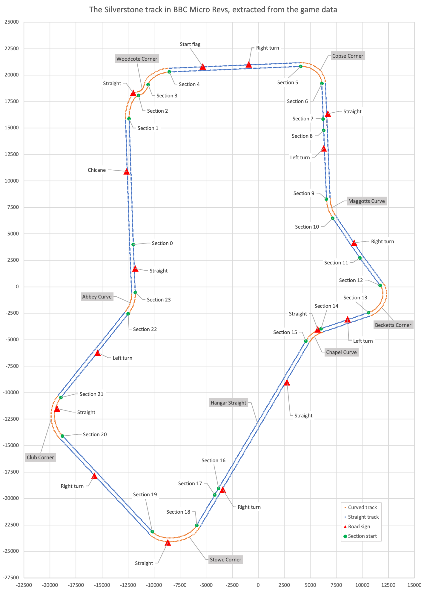
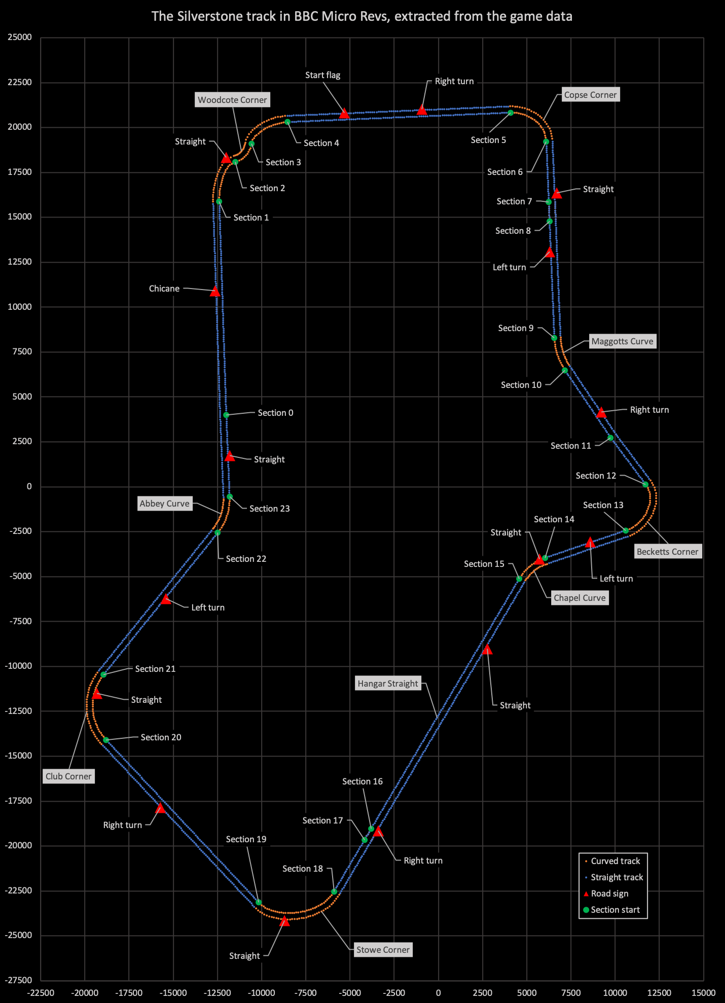

The track is split into 24 sections, numbered from 0 to 23, and you can see the starting points of each section in the picture above. (You can also see segment dots and road sign triangles; we'll cover segments below, but see the deep dive on road signs for more on the latter.)
Section numbers increase as we drive clockwise round the circuit, and are either straight (blue in the above picture) or curved (orange). Matching the sections to the map that comes bundled with the game, we get the following:
| Number | Shape | Description |
|---|---|---|
| 0 | || | Abbey Curve to Woodcote Corner (2/2) |
| 1 | -> | Woodcote Corner (1/3) |
| 2 | <- | Woodcote Corner (2/3) |
| 3 | -> | Woodcote Corner (3/3) |
| 4 | || | Woodcote Corner to Copse Corner |
| 5 | -> | Copse Corner |
| 6 | || | Copse Corner to Maggotts Curve (1/3) |
| 7 | {} | Copse Corner to Maggotts Curve (2/3) |
| 8 | || | Copse Corner to Maggotts Curve (3/3) |
| 9 | <- | Maggotts Curve |
| 10 | || | Maggotts Curve to Becketts Corner (1/2) |
| 11 | || | Maggotts Curve to Becketts Corner (2/2) |
| 12 | -> | Becketts Corner |
| 13 | || | Becketts Corner to Chapel Curve |
| 14 | <- | Chapel Curve |
| 15 | || | Hangar Straight (1/3) |
| 16 | {} | Hangar Straight (2/3) |
| 17 | || | Hangar Straight (3/3) |
| 18 | -> | Stowe Corner |
| 19 | || | Stowe Corner to Club Corner |
| 20 | -> | Club Corner |
| 21 | || | Club Corner to Abbey Curve |
| 22 | <- | Abbey Curve |
| 23 | {} | Abbey Curve to Woodcote Corner (1/2) |
where each section is one of the following shapes:
- || is a straight section that doesn't curve to the left or right, and has the same gradient throughout the whole section
- {} is a straight section in the sense that it doesn't curve to the left or right, but the gradient changes within the section
- -> is a section that curves to the right
- <- is a section that curves to the left
To ensure the track design is available at 16-bit accuracy, the game encodes the start coordinates of each track section using signed 16-bit integers. For 3D coordinates, Revs uses a standard left-handed axis system, which is exactly the same as in Aviator and Elite. This means that when we are looking at the screen, the x-axis runs from left to right, the y-axis runs from down to up, and the z-axis points into the screen. In terms of the track's coordinates in the 3D world, the y-axis gives us the track elevation, while the x-axis is our longitude (west to east) and the z-axis is our latitude (south to north).
For the coordinates of each track section, the data file contains one set of coordinates for the inner track verge and another for the outer verge. Specifically, the coordinates for each section are stored in the track data file as follows:
                        [ (xTrackSectionIHi xTrackSectionILo) ]
  Inner verge starts at [ (yTrackSectionIHi yTrackSectionILo) ]
                        [ (zTrackSectionIHi zTrackSectionILo) ]

                        [ (xTrackSectionOHi xTrackSectionOLo) ]
  Outer verge starts at [ (yTrackSectionIHi yTrackSectionILo) ]
                        [ (zTrackSectionOHi zTrackSectionOLo) ]
These are stored in the two track section data blocks, which are split into part 1 and part 2. We can fetch section coordinates from the track data using the GetSectionCoords routine.
The start coordinates of the inner and outer verges of each section are always at the same elevation, so although the track goes up and down as we drive through different sections and segments, it always remains level in terms of left-to-right camber across the track. You can see this in the above, as the section's inner and outer coordinates share the same y-coordinate (the y-axis being the axis of elevation).
As there are up to 26 sections in the track data file (only 24 of which are used by Silverstone), we need this much memory to store the coordinates for the track section starting points:
26 sections * 5 coordinates * 2 bytes = 260 bytes
This doesn't save any memory over the standard approach of storing all data as 16-bit, but now that we have our sections defined, we can encode all the other coordinate data in the track file using 8-bit signed vectors. Let's take a look at the most important of these - the segment vectors.
Track segments
--------------
Each of the 24 sections described above is split into multiple segments, with a total of 1024 segments making up the whole track. You can see the segments in the track image; here it is again.


Every single tiny blue or orange dot along the verges of the track in the above picture represents one of these track segments. You can see them as you drive around in-game, as each segment corresponds to a single coloured mark along the track verge (so each black, white or red mark maps onto exactly one segment). This is what I mean:
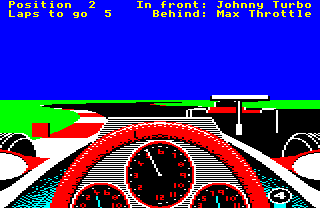
Each one of those red-and-white marks along the track verge is the left edge of one of the 1024 track segments that make up the track. The segments are effectively horizontal strips across the track, one after the other, with the ends coloured to make the verge marks.
The shape of each of these segments is defined by the segment vectors, which can be found in the xTrackSegmentI, yTrackSegmentI, zTrackSegmentI, xTrackSegmentO and zTrackSegmentO tables in the track data file. Each of these tables contains 256 entries, though the last entry is not used. Between them, these five tables define 255 8-bit 3D vectors.
So how do these vector tables manage to squeeze in enough information to encode 3D coordinates for all 1024 segments? There are two rather clever optimisations at play here; let's take a look at what's involved.
Efficient encoding
------------------
The first optimisation is that instead of storing the segment shapes as 16-bit coordinates, we instead store the vectors between neighbouring segments, i.e. the vectors to get from one segment to the next (let's call them "segment vectors"). Our segments are pretty close together - we calculated their average size at about 4.6m earlier - so can we fit these segment vectors into an 8-bit coordinate system without losing any accuracy?
It turns out that we can. In the game's 16-bit coordinate system, we already worked out that each vertical coordinate represents 1700m / 44,549 = 0.0382m = 3.8cm, but how big would the coordinates be in an 8-bit system? The answer is to multiply the size by 256, the maximum value of an 8-bit integer, which gives 256 * 0.0382m = 9.8m. If we think of our 16-bit coordinate system as being the same as 8-bit coordinate system, with each of those coordinates being split again into another 8-bit coordinate system, then each of the embedded 8-bit coordinate systems would cover a 9.8m by 9.8m square.
So as long as our neighbouring segments are within 9.8m of each other, we can encode the vectors between consecutive segments as 8-bit vectors, without losing any of the accuracy of the original 16-bit coordinate system. Given that the average size of a segment is 4.6m, this fits nicely, and it means we can ditch our six-byte 16-bit track segment coordinates and store three-byte 8-bit vectors instead.
Let's see how this works. As with the section coordinates, we have two sets of segment vectors, one for the inner verge, and the other for the outer verge. xTrackSegmentI, yTrackSegmentI and zTrackSegmentI contain the inner segment vector for each segment, with each coordinate being a signed 8-bit value like this:
                         [ xTrackSegmentI ]
  Inner segment vector = [ yTrackSegmentI ]
                         [ zTrackSegmentI ]
xTrackSegmentO and zTrackSegmentO contain the outer segment vector for each segment, with each coordinate again being a signed 8-bit value:
                         [ xTrackSegmentO ]
  Outer segment vector = [ yTrackSegmentI ]
                         [ zTrackSegmentO ]
We can fetch segment vectors from the track data using the GetSegmentVector routine.
Together these two vectors define each segment's coordinates, but they behave quite differently. The inner segment vector is the vector along the inner verge of the track, from the previous segment to the current one. Meanwhile, the outer segment vector is the vector from the inner verge of the segment to the outer verge (i.e. across the track). As the track is level from the inner to the outer verge, the outer segment vector can reuse the y-coordinate from the inner vector in yTrackSegmentI.
Incidentally, on the subject of track elevation, this is what the track looks like when we plot the y-axis values for each of the 1024 segments:
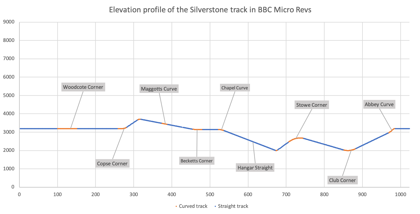
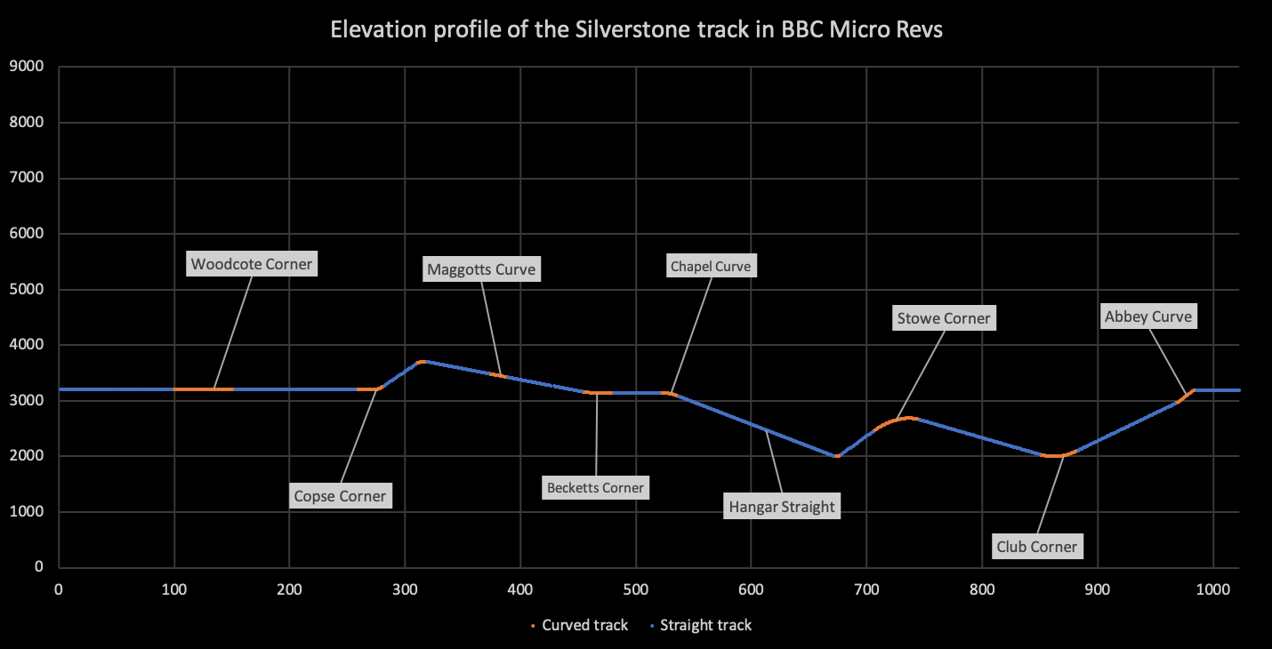

See what I mean about the dips and crests? Segments might be level from one side of the track to the other, but as each segment is modelled in three dimensions with its own y-coordinate, the track can therefore support a different elevation for each of the 1024 segments along the track. The inclines are really something in this game, and other games just didn't go this far when modelling their tracks. Geoff Crammond really went for it with Revs.
Anyway, back to the segment vectors. To calculate the 3D coordinates for a specific track segment in a curved section, we take the start coordinates for the section, and add all the segment vectors for that section in order, until we reach the segment we're after, by which point we have the coordinates of the inner verge of the segment. Then, to get the outer verge's coordinate, we simply add that segment's outer segment vector.
As an example, say we are interested in calculating the 3D coordinates for the outside verge of segment 7 in curved section 18 (where both numbering schemes start from zero, i.e. the track data starts at section 0, segment 0). To do this, we take the 3D coordinates for the start of section 18, and then add the first seven segment vectors for that section, to get the 3D coordinates for the inner verge of segment 7. We then add the seventh outer segment vector to get the 3D coordinates for the outer verge of segment 7, and we are done.
So what about straight sections? Well, they're subject to the second optimisation, one that makes a huge difference to the size of the data file. You'll remember that the track is made up of 1024 segments... but we only have 255 segment vectors. Where do the missing segment vectors come from?
It turns out that each straight section only has one segment vector in the track data file, and the code calculates the coordinates for each segment in the section by taking the starting point of the section, as normal, and simply adding the same segment vector the correct number of times. For example, to get the coordinates for segment 7 in straight section 19, we would simply add section 19's segment vector to the section's starting coordinates seven times. In essence, the segment vector for a straight section is just the vector from the section's start point to the start of segment 1, and we just add on additional segments of the same shape to build up the section. We know the number of segments in each section from the trackSectionSize variable, so we know when to stop adding segment vectors and move on to the next section.
The UpdateCurveVector and UpdateVectorNumber routines take care of fetching the next vector, depending on the shape of the section. For curves, they update the vector number (stored in thisVectorNumber) to the curve's next segment vector, while for straight sections they leave thisVectorNumber alone.
Given these two optimisations, we can encode each segment vector table using 256 entries (though the last entry is not used), and each entry is an 8-bit signed integer, taking up just one byte. So the segment vectors take up this much space:
256 segment vectors * 5 coordinates * 1 byte = 1,280 bytes
Using this information, and the section starting coordinates, the game can calculate the 3D coordinates of any segment's inner or outer verge, all with full 16-bit accuracy (see the GetTrackSegment routine for the gory details). The section coordinates take up 280 bytes, while the segment vectors take up 1,280 bytes, so that's a total of 1,560 bytes. There's a handful of other values that we need as well, though these are all very efficient:
- trackSectionFlag contains a one-bit flag for each section that specifies whether it is curved or straight, so that's another 26 bytes (and these flags contain lots of other useful information too).
- trackSectionFrom is the number of the first segment vector in each section, so we can jump straight to the relevant segment vectors for a given section. This is another 26 bytes.
- trackSectionSize gives us the length of each track section in terms of segments, so that's 26 bytes as well.
- trackSectionCount contains the total number of track sections * 8, which is just one byte.
- trackVectorCount contains the total number of segment vectors in the segment vector tables, which is again one byte.
- trackLength gives us the length of the full track in terms of segments, using two bytes for this 16-bit number.
And that's it, giving us a grand total of 1,641 bytes to store the entire track at 16-bit accuracy. That's about 13.4% of the memory we would need to store all these coordinates as full 16-bit values; quite the saving.
And just to show how accurate the track is, here's the track data superimposed on a satellite image of the track:
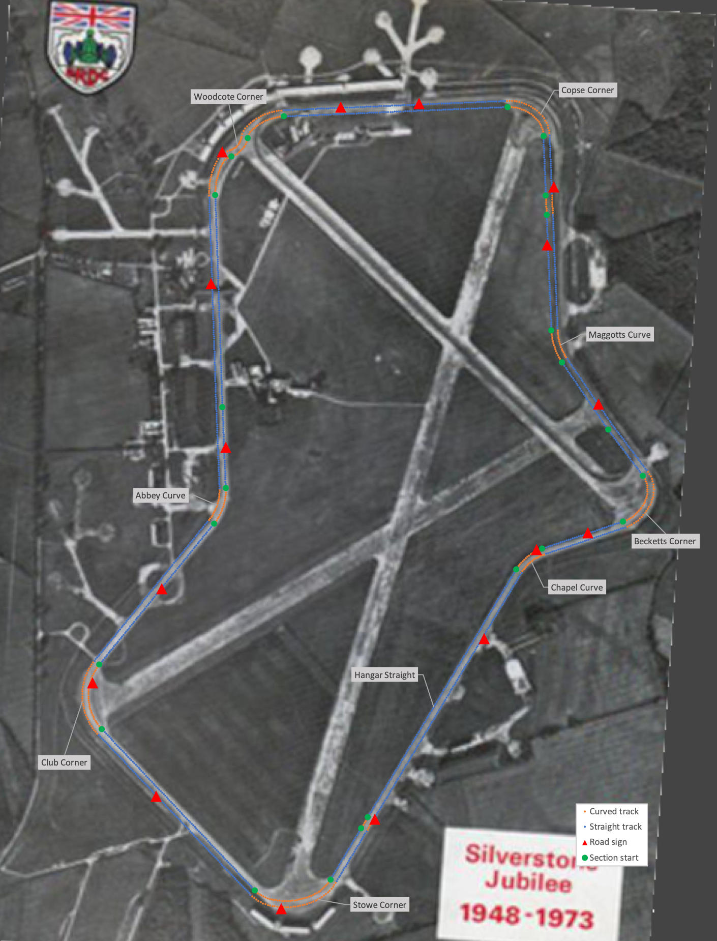
I have no idea how this satellite image relates to the one that Geoff Crammond used to trace the track for Revs, but it's clear that he managed to build something impressive from all those sections and segments: a super-accurate, realistic model of 1980s Silverstone, all in a handful of bytes. "Best and most reliable" is indeed a good description...