Details of the 13 objects that make up the signs, flags, markers and cars
The main driving view in Revs is a relatively straightforward composition. In the distance is the cloudless, blue sky; then just below the horizon is the track with its red-and-white verges, black bitumen and grassy surroundings; and finally there are various objects spinning past, from road signs and corner markers and starting flags by the track edge, to competitors' cars crowding the racing line around the bends. In this article, we're going to look at each of these objects in detail.
There are 13 different types of object in Revs. These objects are all fully scalable, so each of them can be shown at any distance with different levels of detail, all while using the same object definitions - see the deep dive on scaling objects with scaffolds for details. Individually each object is 2D, but some of them can be put together to create really convincing 3D objects - see the deep dive on drawing a 3D car from 2D parts for more on that. And despite this complexity, each object is drawn efficiently using nothing more than vertical edges, which fit nicely into the strip-based structure of the screen buffer - see the deep dive on creating objects from edges for more about the object-drawing process, and the deep dive on drawing the track view for details about the screen buffer.
We'll take a tour through all the different object types in a moment, but first let's look at how the object system works.
The object system
-----------------
There are 13 types of object in Revs, each with its own object definition. The different object types are numbered 0 to 12, and the type of the object currently being drawn is stored in the objectType variable. The object types are as follows (the links will take you down to the relevant object type definition below):
- Four-object car, front tyres
- Four-object car, body and helmet
- Four-object car, rear tyres
- Four-object car, rear wing
- Standard car
- Distant car
- Corner marker
- Straight sign
- Start flag
- Blank road sign
- Chicane road sign (or the hairpin road sign in some tracks)
- Right turn road sign
- Left turn road sign
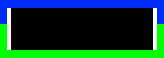
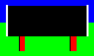
Each object type is made up of one or more object parts. When drawing an object, we draw each part individually and in order, so parts that are drawn first can be partially obscured by parts that are drawn later. For example, take a look at object type 0, which displays the front tyres of the four-object car:

The red rectangle is the last object part to be drawn, so it overlaps the black-and-white tyres on either side.
Each object part has its own set of data in the object data tables, which define the size and colour of the object part. Most object parts are simple rectangles, and they are defined by values for the top, bottom, left and right edges of the rectangle, plus the colour of the rectangle.
The shape and size of each object part is defined in the object data tables at objectTop, objectBottom, objectLeft and objectRight. These tables are indexed by the objectIndex table, which lets us convert an object type into a range of indexes that can be used to pull the relevant values from the data tables.
The object data tables contain dimensions that are relative to the centre of the object, with each dimension being stored as one of a set of scaffold measurements. The scaffold system is described in detail in the deep dive on scaling objects with scaffolds, but for the purposes of this article, you can think of each object type as being drawn on a scalable 65-by-65 grid, with the axes ranging from -32 to +32.
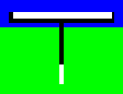
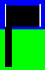
Each object part's colour is defined in the objectColour table. Each entry in objectColour defines two colours for the relevant object part: the edge colour (in bits 2-3) and the fill colour (in bits 0-1). Each object part is a rectangle, but of the four edges, only the left and right edges are drawn. Object type 5, which shows a distant car, is a good example of an object with just one object part:
As you can see, the rectangle has left and right edges, but nothing at the top or bottom. Objects that appear to have top or bottom edges, like the tyres in object type 0 above, implement them using individual object parts for the edges (so object type 0 has two dedicated object parts for the two white lines at the tops of the tyres). So from left to right, each object part is drawn as a left edge (in the edge colour), then the inside of the rectangle (in the fill colour), and then a right edge (in the edge colour).
It's worth noting that the four colours used in the object definitions are logical colours. The default mapping is 0 = black, 1 = red, 2 = white and 3 = green, but this can be changed before calling the display routines to shows objects like cars and corner markers in different colours. This enables different drivers to have different car colours, and for the corner flags to be white on the approach to a corner, and red on the corner itself.
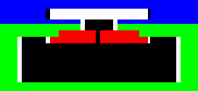
If bit 4 of objectColour is set, then the object's outside edge is drawn in the fill colour, which effectively hides it by merging it with the rectangle's fill. An outside edge is defined as a left edge in the left half of the screen, or a right edge in the right half of the screen. This gives objects like the corner marker (object type 6) an asymmetric appearance, like this:

The marker has a black edge on the track side of the marker (the inside edge), but a white edge on the side away from the track (the outside edge); the example above is of a marker on the right side of the track. This logic works correctly on both sides of the track without needing to change the object definition in any way.
Some object parts are more complicated than simple rectangles and use two sets of data to create four-edge object parts. This feature is only used by object types 2 and 4, where it gives the cars red and white central sections. Here's object type 2, which shows the rear tyres of the four-object car:
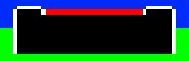
The four-edge object part is the strip along the top of the tyres, which has three sections (black, red and black) with white edges. Four-edge object parts are signalled by bit 7 of objectColour being set, in which case the next data entries from objectTop, objectBottom, objectLeft and objectRight and objectColour define the positions and colours of the two extra edges in the object part.
Incidentally, bit 6 of objectColour being set indicates that this is last object part in each object type. This saves us having to store an end index for each part - the objectIndex table just contains the index of the first object part for each object type, and the code stops when it reaches a part with bit 6 of objectColour set. This saves a few precious bytes without affecting performance.
Finally, some of the object types below are displayed in groups of multiple objects, as follows:
- The first four object types (0 to 3) work together to create a 3D car that is made up of four objects - see the deep dive on drawing a 3D car from 2D parts for details. This is only done for the nearest car to us, and only when we are facing forwards along the track; all other cars use either object type 4 (for close cars) or object type 5 (for distant cars).
- The road sign object types (9 to 12) work in pairs. When asked to draw an object of type 10 to 12 (chicane, right turn or left turn), the game first draws a blank, white sign using an object of type 9, and then it draws the sign's contents by drawing object type 10, 11 or 12 over the top (though only if we are facing forwards, so road signs are blank on the back). See object types 9 to 12 below for more on this.
Now that's out of the way, let's take a look at each of the different object types in more detail.
Object type 0: Four-object car, front tyres
-------------------------------------------
In the four-object car, this is the furthest of the four objects and the first to be drawn, and shows the car's front tyres. The centre of the object is high up so the tyres are low down within the resulting 3D car. See the deep dive on drawing a 3D car from 2D parts for an explanation of how the four-object car works.
This is what object type 0 looks like at a reasonable distance (top), and close up (bottom):

| Part | Top | Bottom | Left | Right | Edge colour | Fill colour |
|---|---|---|---|---|---|---|
| 0 | -4 | -5 | -22 | -18 | White | White |
| 1 | -4 | -5 | +18 | +22 | White | White |
| 2 | -5 | -17 | -24 | -16 | White | Black |
| 3 | -5 | -17 | +16 | +24 | White | Black |
| 4 | -8 | -17 | -18 | +18 | Red | Red |
If we draw all five parts, we get the following design, where the scaffold measurements are shown around the side, and * indicates the centre of the object:
                       -22  -18        0        +18  +22

                                       *                           0

  Parts 0, 1 ->         +---+                     +---+           -4
                      +-+---++                   ++---+-+         -5
  Parts 2, 3 ->       |      |                   |      |
                      |     ++-------------------++     |         -8
  Part 4 ->           |     |                     |     |
                      |     |                     |     |
                      +-----+---------------------+-----+        -17

                     -24   -16         0         +16   +24
Object type 1: Four-object car, body and helmet
-----------------------------------------------
In the four-object car, this is the second of the four objects to be drawn, and shows the car's body and the driver's helmet. The centre of the object is low down so the helmet peeks above the rear tyres in the resulting 3D car. See the deep dive on drawing a 3D car from 2D parts for an explanation of how the four-object car works.
This is what object type 1 looks like at a reasonable distance (top), and close up (bottom):


| Part | Top | Bottom | Left | Right | Edge colour | Fill colour |
|---|---|---|---|---|---|---|
| 0 | +5 | +2 | -5 | +5 | White | Black |
| 1 | +2 | -1 | -8 | +8 | White | Black |
| 2 | -1 | -5 | -12 | +12 | White | Red |
| 3 | +6 | +5 | -2 | +2 | White | White |
If we draw all four parts, we get the following design, where the scaffold measurements are shown around the side, and * indicates the centre of the object:
                          -8      -2       +2      +8

  Part 3 ->                        +-------+                      +6
                               +---+-------+----+                 +5
  Part 0 ->                    |                |
                           +---+----------------+---+             +2
  Part 1 ->                |                        |
                           |           *            |              0
                      +----+------------------------+----+        -1
                      |                                  |
  Part 2 ->           |                                  |
                      |                                  |
                      +----------------------------------+        -5

                    -12       -5       0       +5       +12
Object type 2: Four-object car, rear tyres
------------------------------------------
In the four-object car, this is the third of the four objects to be drawn, and shows the car's rear tyres. The centre of the object is high up so the tyres are low down within the resulting 3D car, allowing the helmet to be seen above the rear end. See the deep dive on drawing a 3D car from 2D parts for an explanation of how the four-object car works.
This is what object type 2 looks like at a reasonable distance (top), and close up (bottom):

| Part | Top | Bottom | Left | Right | Edge colour | Fill colour |
|---|---|---|---|---|---|---|
| 0 | -3 | -5 | -26 | -16 | White | Black |
| 2nd edge | - | - | - | +16 | - | Red |
| 3rd edge | - | - | - | +26 | Red | - |
| 2 | -5 | -17 | -26 | +26 | White | Black |
| 3 | -2 | -3 | -24 | -18 | White | White |
| 4 | -2 | -3 | +18 | +24 | White | White |
If we draw all five parts, we get the following design, where the scaffold measurements are shown around the side, part 0 is a four-edge object part that uses the values that would otherwise make up part 1, and * indicates the centre of the object:
                      -24  -18         0         +18  +24

                                       *                           0

  Parts 3, 4 ->         +---+                     +---+           -2
                      +-------+-----------------+-------+         -3
  Part 0 (x4) ->      |       |                 |       |
                      +-------+-----------------+-------+         -5
                      |                                 |
                      |                                 |
  Part 2 ->           |                                 |
                      |                                 |
                      |                                 |
                      +---------------------------------+        -17

                     -26     -16       0       +16     +26
Object type 3: Four-object car, rear wing
-----------------------------------------
In the four-object car, this is the closest of the four objects and the last to be drawn, and shows the car's rear wing. The centre of the object is positioned so the white part of the tail touches the ground at the rear of the car, while the wing itself rises above the chassis. See the deep dive on drawing a 3D car from 2D parts for an explanation of how the four-object car works.
This is what object type 3 looks like at a reasonable distance (top), and close up (bottom):

| Part | Top | Bottom | Left | Right | Edge colour | Fill colour |
|---|---|---|---|---|---|---|
| 0 | +6 | +4 | -16 | +16 | Black | White |
| 1 | +4 | +3 | -16 | +16 | Black | Black |
| 2 | +3 | -10 | -1 | +1 | Black | White |
| 3 | -10 | -16 | -1 | +1 | White | White |
If we draw all four parts, we get the following design, where the scaffold measurements are shown around the side, and * indicates the centre of the object:
                      -16              0              +16

                       +-------------------------------+       +6
  Part 0 ->            |                               |
                       +-------------------------------+       +4
  Part 1 ->            +--------------+-+--------------+       +3
                                      | |
                                      | |
                                      |*|                       0
                                      | |
                                      | |
  Part 2 ->                           | |
                                      | |
                                      | |
                                      | |
                                      +-+                     -10
                                      | |
  Part 3 ->                           | |
                                      | |
                                      +-+                     -16
Object type 4: Standard car
---------------------------
This object type is used for all nearby cars apart from the nearest (which is shown as the four-object car above). If our car has spun round and is pointing the wrong way down the track, then this object type is used for all nearby cars including the nearest, as the four-object car only works when seen from behind.
This is what object type 4 looks like at a reasonable distance (top), and close up (bottom):

| Part | Top | Bottom | Left | Right | Edge colour | Fill colour |
|---|---|---|---|---|---|---|
| 0 | +3 | -1 | -6 | +6 | White | Black |
| 1 | -1 | -5 | -12 | +12 | Red | Red |
| 2 | -3 | -5 | -26 | -16 | White | Black |
| 2nd edge | - | - | - | +16 | - | Red |
| 3rd edge | - | - | - | +26 | Red | - |
| 4 | -5 | -17 | -26 | +26 | White | Black |
| 5 | +1 | -5 | -1 | +1 | Black | White |
| 6 | +6 | +3 | -16 | +16 | Black | White |
If we draw all seven parts, we get the following design, where the scaffold measurements are shown around the side, part 2 is a four-edge object part that uses the values that would otherwise make up part 3, part 5 is the black line up the middle of the object, and * indicates the centre of the object:
                          -16          0          +16

                           +-----------------------+                 +6
  Part 6 ->                |                       |
                           +------+---------+------+                 +3
  Part 0 ->                       |         |
                                  |   +-+   |
  Part 5 ->                       |   |*|   |                         0
                             +----+---+ +---+----+                   -1
  Part 1 ->                  |        | |        |
                  +--------+-+--------+ +--------+-+--------+        -3
  Part 2 (x4) ->  |        | :        | |        : |        |
                  +--------+-+--------+-+--------+-+--------+        -5
                  |                                         |
                  |                                         |
  Part 4 ->       |                                         |
                  |                                         |
                  |                                         |
                  +-----------------------------------------+       -17

                 -26        -12      -1 +1        +12      +26
Object type 5: Distant car
--------------------------
This object type is used for distant cars, to simplify the drawing process when a car is too far away for any of the details of object type 4 to be visible. The centre of the object is high up, so the car is shown quite low down on the track and stays below the horizon.
This is what object type 5 looks like at a reasonable distance (top), and close up (bottom):

| Part | Top | Bottom | Left | Right | Edge colour | Fill colour |
|---|---|---|---|---|---|---|
| 0 | -3 | -17 | -26 | +26 | White | Black |
If we draw the object, we get the following design, where the scaffold measurements are shown around the side, and * indicates the centre of the object:
                      -26              0              +26

                                       *                        0

                       +-------------------------------+       -3
                       |                               |
  Part 0 ->            |                               |
                       |                               |
                       +-------------------------------+      -17
Object type 6: Corner marker
----------------------------
This object type is a simple rectangle that's used for the corner markers. It's a good example of the feature that lets us merge outside edges into the fill colour, as it changes the look of the corner markers depending on which side of the track they appear. Specifically, the marker has a black edge on the track side of the marker (the inside edge), but not on the side away from the track (the outside edge). This works on both sides of the track without needing to change the object definition in any way.
This is what object type 6 looks like at a reasonable distance (top), and close up (bottom):

| Part | Top | Bottom | Left | Right | Edge colour | Fill colour |
|---|---|---|---|---|---|---|
| 0 | +16 | +1 | -10 | +10 | Black * | White |
The * in the above table means that for outside edges, we use the fill colour for the colour of the edge, rather than the edge colour. An outside edge is defined as a right edge in the eight half of the screen, or a left edge in the left half of the screen. This feature is controlled by bit 4 of the objectColour entry for this part.
If we draw the object, we get the following design, where the scaffold measurements are shown around the side, and * indicates the centre of the object:
                           -10         0         +10


                            +---------------------+           +16
                            |                     |
                            |                     |
                            |                     |
  Part 0 ->                 |                     |
                            |                     |
                            |                     |
                            |                     |
                            +---------------------+            +1
                                       *                        0
Object type 7: Straight sign
----------------------------
This object type is the sign that we see on the right of the track at the start of the practice and qualifying laps. It signifies the start of a straight portion of track. Its legs are asymmetric, with the red legs having a black border on the inside edges only.
This is what object type 7 looks like at a reasonable distance (top), and close up (bottom):

| Part | Top | Bottom | Left | Right | Edge colour | Fill colour |
|---|---|---|---|---|---|---|
| 0 | +20 | -8 | -28 | +28 | White | Black |
| 1 | -8 | -18 | -20 | -16 | Black * | Red |
| 2 | -8 | -18 | +16 | +20 | Black * | Red |
The * in the above table means that for outside edges, we use the fill colour for the colour of the edge, rather than the edge colour. An outside edge is defined as a right edge in the eight half of the screen, or a left edge in the left half of the screen. This feature is controlled by bit 4 of the objectColour entry for this part.
If we draw all three parts, we get the following design, where the scaffold measurements are shown around the side, and * indicates the centre of the object:
                  -28                  0                  +28

                   +---------------------------------------+     +20
                   |                                       |
                   |                                       |
  Part 0 ->        |                                       |
                   |                                       |
                   |                   *                   |       0
                   |                                       |
                   +-------+---+---------------+---+-------+      -8
                           |   |               |   |
  Parts 1, 2 ->            |   |               |   |
                           |   |               |   |
                           +---+               +---+             -18

                         -20   -16           +16   +20
Object type 8: Start flag
-------------------------
This object type is the flag to the left of the starting line. Not surprisingly, it only appears once in the whole track.
This is what object type 8 looks like at a reasonable distance (top), and close up (bottom):

| Part | Top | Bottom | Left | Right | Edge colour | Fill colour |
|---|---|---|---|---|---|---|
| 0 | +3 | -18 | -2 | +2 | Black | Black |
| 1 | +16 | +3 | -2 | +16 | White | Black |
If we draw both parts, we get the following design, where the scaffold measurements are shown around the side, and * indicates the centre of the object. This is the only asymmetrical design in terms of overall layout (the sign contents are also asymmetric, but they are shown within a symmetrical road sign). In this object, the flag is offset to the right of the centre line:
                                       0             +16

                                     +----------------+     +16
                                     |                |
                                     |                |
  Part 1 ->                          |                |
                                     |                |
                                     +---+------------+      +3
                                     |   |
                                     | * |                    0
                                     |   |
                                     |   |
  Part 0 ->                          |   |
                                     |   |
                                     |   |
                                     |   |
                                     |   |
                                     |   |
                                     +---+                  -18

                                    -2   +2
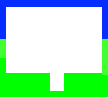
Object type 9: Blank road sign
------------------------------
This object type is the blank sign on which the road signs in object types 10, 11 and 12 are drawn. For the road signs, this object is drawn first, and then the contents are drawn over the top of the blank sign. Object types 10 to 12 only contain the black contents of the sign, not the white background.
This is what object type 9 looks like at a reasonable distance (top), and close up (bottom):

| Part | Top | Bottom | Left | Right | Edge colour | Fill colour |
|---|---|---|---|---|---|---|
| 0 | +12 | -10 | -16 | +16 | White | White |
| 1 | -10 | -16 | -3 | +3 | Black * | White |
If we draw both parts, we get the following design, where the scaffold measurements are shown around the side, and * indicates the centre of the object:
                      -16              0              +16

                       +-------------------------------+      +12
                       |                               |
                       |                               |
                       |                               |
                       |                               |
  Part 0 ->            |                               |
                       |               *               |
                       |                               |
                       |                               |
                       |                               |
                       +-------------+---+-------------+      -10
                                     |   |
  Part 1 ->                          |   |
                                     +---+

                                    -3   +3
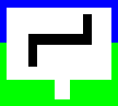
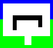
Object type 10: Chicane road sign
---------------------------------
This object type contains the contents for the chicane road sign. This object is only drawn once the white background in object type 9 has been drawn. If we are facing the wrong way along the track, the sign contents are not drawn, so the road signs are one-sided.
This is what object type 10 looks like at a reasonable distance (top), and close up (bottom):

| Part | Top | Bottom | Left | Right | Edge colour | Fill colour |
|---|---|---|---|---|---|---|
| 0 | +4 | +1 | -10 | +10 | Black | Black |
| 1 | +1 | -6 | -10 | -9 | Black | Black |
| 2 | +10 | +4 | +9 | +10 | Black | Black |
If we draw all three parts, we get the following design, where the scaffold measurements are shown around the side, and * indicates the centre of the object. This object doesn't contain the sign itself, which comes from object type 9, but this is what they look like together:
                           -10         0         +10

                       +-------------------------------+
                       |                               |
                       |                       +--+    |      +10
  Part 2 ->            |                       |  |    |
                       |    +------------------+--+    |       +4
  Part 0 ->            |    |                     |    |
                       |    +--+------------------+    |       +1
  Part 1 ->            |    |  |                       |
                       |    |  |                       |
                       |    +--+                       |       -6
                       +-------------+---+-------------+
                                     |   |
                                     |   |
                                     +---+

                              -9              +9
Object type 10a: Hairpin road sign
----------------------------------
This object type contains the contents for the hairpin road sign. The hairpin sign is only used in the Brands Hatch, Nürburgring and Oulton Park tracks, where the top and bottom coordinates of part 2 of the chicane road sign object are modified so the right-hand vertical bar is below the horizontal line rather than above it. This turns the sign into a hairpin; see the deep dive on secrets of the extra tracks for details of the extra track modification process. As with the chicane sign, this object is only drawn once the white background in object type 9 has been drawn. If we are facing the wrong way along the track, the sign contents are not drawn, so the road signs are one-sided.
This is what object type 10a looks like at a reasonable distance (top), and close up (bottom):

| Part | Top | Bottom | Left | Right | Edge colour | Fill colour |
|---|---|---|---|---|---|---|
| 0 | +4 | +1 | -10 | +10 | Black | Black |
| 1 | +1 | -6 | -10 | -9 | Black | Black |
| 2 | +1 | -4 | +9 | +10 | Black | Black |
If we draw all three parts, we get the following design, where the scaffold measurements are shown around the side, and * indicates the centre of the object. This object doesn't contain the sign itself, which comes from object type 9, but this is what they look like together:
                           -10         0         +10

                       +-------------------------------+
                       |                               |
                       |                               |
                       |                               |
                       |    +------------------+--+    |       +4
  Part 0 ->            |    |                     |    |
                       |    +--+------------------+    |       +1
  Part 2 ->            |    |  |               |  |    |
                       |    |  |               +--+    |       -4
  Part 1 ->            |    +--+                       |       -6
                       +-------------+---+-------------+
                                     |   |
                                     |   |
                                     +---+

                              -9              +9
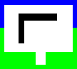
Object type 11: Right turn road sign
------------------------------------
This object type contains the contents for the right turn road sign. This object is only drawn once the white background in object type 9 has been drawn. If we are facing the wrong way along the track, the sign contents are not drawn, so the road signs are one-sided.
This is what object type 11 looks like at a reasonable distance (top), and close up (bottom):

| Part | Top | Bottom | Left | Right | Edge colour | Fill colour |
|---|---|---|---|---|---|---|
| 0 | +8 | +5 | -10 | +8 | Black | Black |
| 1 | +5 | -6 | -10 | -8 | Black | Black |
If we draw both parts, we get the following design, where the scaffold measurements are shown around the side, and * indicates the centre of the object. This object doesn't contain the sign itself, which comes from object type 9, but this is what they look like together:
                           -10         0      +8

                       +-------------------------------+
                       |                               |
                       |    +------------------+       |       +8
  Part 0 ->            |    |                  |       |
                       |    +--+---------------+       |       +5
                       |    |  |                       |
  Part 1 ->            |    |  |                       |
                       |    |  |                       |
                       |    +--+                       |       -6
                       |                               |
                       +-------------+---+-------------+
                                     |   |
                                     |   |
                                     +---+

                              -8
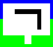
Object type 12: Left turn road sign
-----------------------------------
This object type contains the contents for the left turn road sign. This object is only drawn once the white background in object type 9 has been drawn. If we are facing the wrong way along the track, the sign contents are not drawn, so the road signs are one-sided.
This is what object type 12 looks like at a reasonable distance (top), and close up (bottom):

| Part | Top | Bottom | Left | Right | Edge colour | Fill colour |
|---|---|---|---|---|---|---|
| 0 | +8 | +5 | -8 | +10 | Black | Black |
| 1 | +5 | -6 | +8 | +10 | Black | Black |
If we draw both parts, we get the following design, where the scaffold measurements are shown around the side, and * indicates the centre of the object. This object doesn't contain the sign itself, which comes from object type 9, but this is what they look like together:
                              -8       0         +10

                       +-------------------------------+
                       |                               |
                       |       +------------------+    |       +8
  Part 0 ->            |       |                  |    |
                       |       +---------------+--+    |       +5
                       |                       |  |    |
  Part 1 ->            |                       |  |    |
                       |                       |  |    |
                       |                       +--+    |       -6
                       |                               |
                       +-------------+---+-------------+
                                     |   |
                                     |   |
                                     +---+

                                              +8