One of the four extra tracks in the Revs 4 Tracks expansion
Snetterton was one of the four new tracks released by Acornsoft as part of the Revs 4 Tracks expansion in late 1985 (the others being Brands Hatch, Donington Park and Oulton Park).
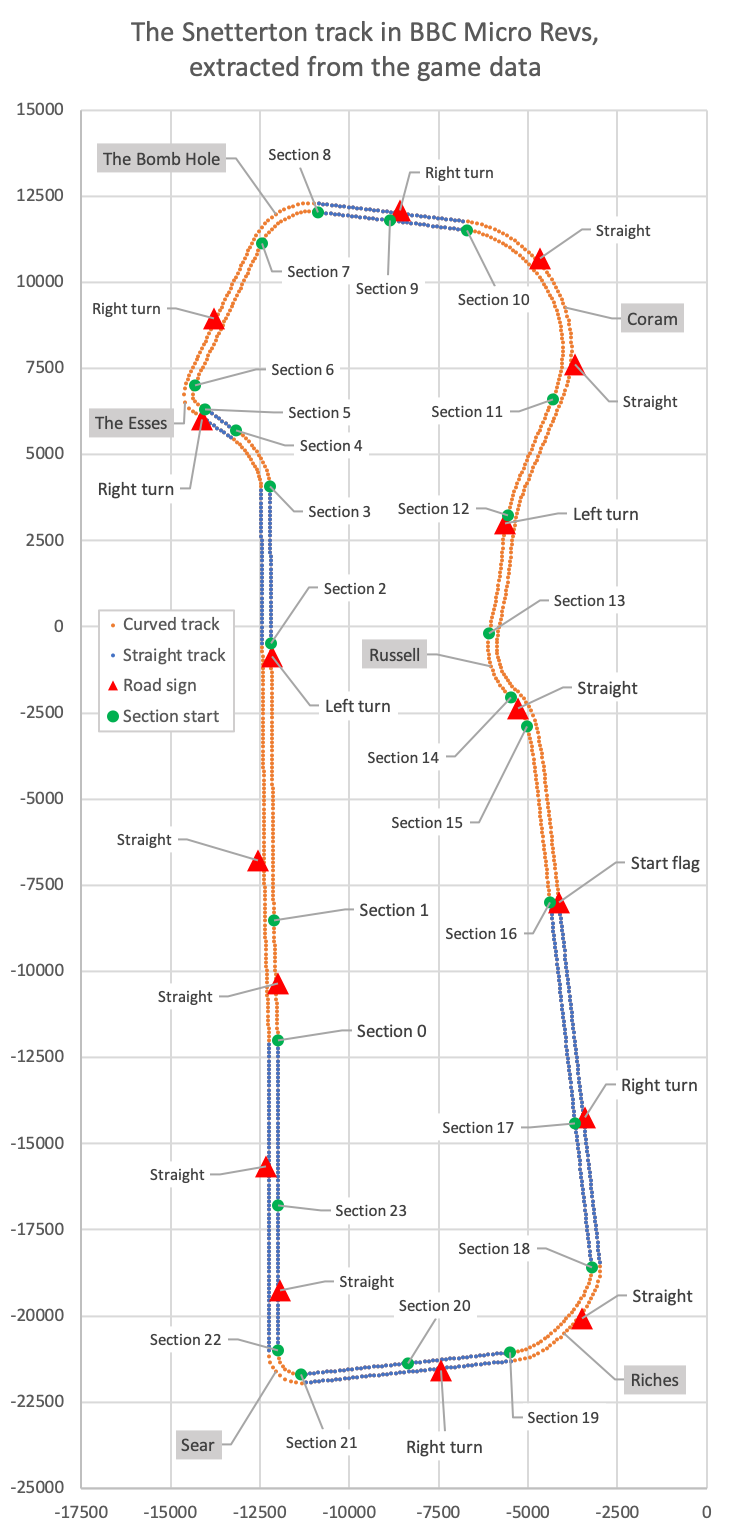
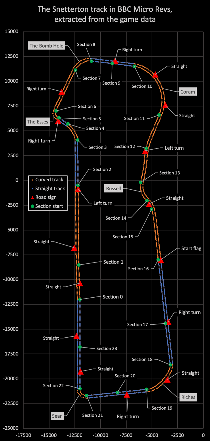
The track looks like this, if we extract the data from the track data file and draw the results:
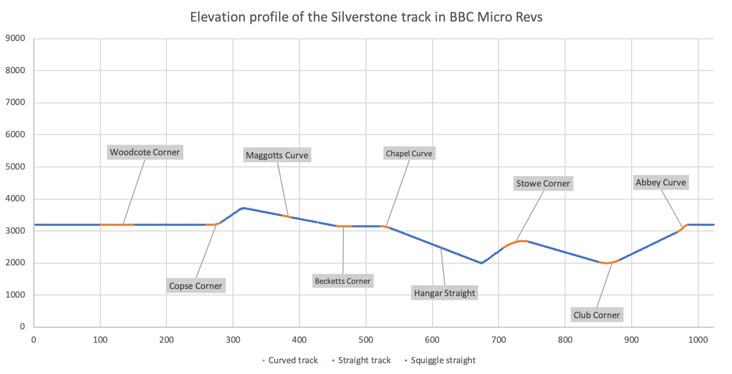
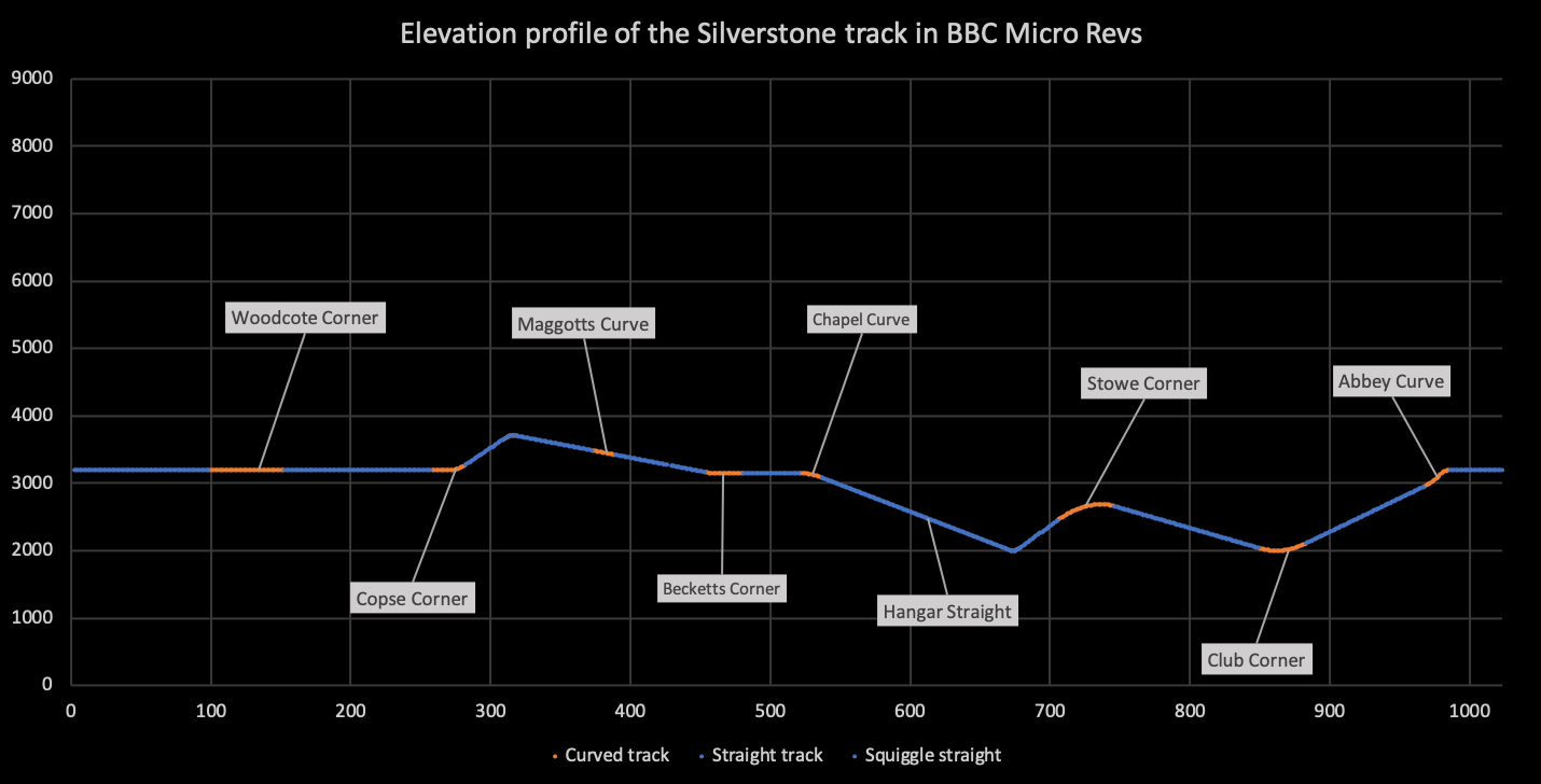
The track's elevation profile looks like this:
The track is broken up into 24 sections, as follows:
| Number | Shape | Description |
|---|---|---|
| 0 | |<-| | Sear to the Esses (3/5) |
| 1 | |->| | Sear to the Esses (4/5) |
| 2 | {} | Sear to the Esses (5/5) |
| 3 | <- | The Esses (1/3) |
| 4 | || | The Esses (2/3) |
| 5 | |->| | The Esses (3/3) |
| 6 | |->| | The Esses to the Bomb Hole |
| 7 | -> | The Bomb Hole |
| 8 | || | The Bomb Hole to Coram (1/2) |
| 9 | || | The Bomb Hole to Coram (2/2) |
| 10 | -> | Coram |
| 11 | |<-| | Coram to Russell (1/2) |
| 12 | |<->| | Coram to Russell (2/2) |
| 13 | <- | Russell |
| 14 | -> | Russell to Riches (1/4) |
| 15 | |->| | Russell to Riches (2/4) |
| 16 | {} | Russell to Riches (3/4) |
| 17 | || | Russell to Riches (4/4) |
| 18 | -> | Riches |
| 19 | || | Riches to Seer (1/2) |
| 20 | || | Riches to Seer (2/2) |
| 21 | -> | Sear |
| 22 | || | Sear to the Esses (1/5) |
| 23 | || | Sear to the Esses (2/5) |
Each section is one of the following shapes:
- || is a straight section that doesn't curve to the left or right, and has the same gradient throughout the whole section
- {} is a straight section in the sense that it doesn't curve to the left or right, but the gradient can differ between sub-sections
- -> consists of sub-sections that all curve to the right
- <- consists of sub-sections that all curve to the left
- |->| consists of sub-sections that are either straight or curve to the right
- |<-| consists of sub-sections that are either straight or curve to the left
- |<->| consists of sub-sections that are either straight or curve to the left or right
See the deep dives on the extra tracks data file format and dynamic track generation in the extra tracks for information on how the extra tracks are constructed, and how the track segment vectors are dynamically generated in the extra tracks. You may also find it useful to read the deep dives on the original track data file format and building a 3D track from sections and segments.
Track generation and shapes
---------------------------
Each track section has lots of associated data, most of which is stored in the two track section data blocks. These are split into part 1 and part 2. See the deep dives on the track data file format and the extra tracks data file format for details.
In the extra track files, track sections are broken up into sub-sections, which are then broken up into segments. Each section therefore has an associated size, given as the number of segments. There is also a track segment vector number, which determines which track segment vectors make up the sections; specifically, it points to the position in the segment vector table where the section's first vector is stored. Note, however, that because the track segment vectors are dynamically generated for this track, the vector number points to the position in the table where the first calculated vector will be stored, rather than pointing to the data itself (as the data is only generated when needed).
Finally, each section has inner and outer coordinates that define the inner and outer track edges at the start of the section. These coordinates share the same y-coordinate, as track sections are level from left to right, so the following table shows the coordinates as (x, z), or longitude and latitude, and the section height is shown separately.
The section data for the Snetterton track is as follows:
| Section | Vector | Size | Segments | Inner coord | Outer coord | Height |
|---|---|---|---|---|---|---|
| 0 | 1 | 29 | 0-28 | (-12000, -12000) | (-12248, -12000) | 5120 |
| 1 | 31 | 67 | 29-95 | (-12115, -8520) | (-12363, -8529) | 5120 |
| 2 | 19 | 38 | 96-133 | (-12184, -480) | (-12432, -483) | 5120 |
| 3 | 18 | 16 | 134-149 | (-12222, 4080) | (-12470, 4077) | 4481 |
| 4 | 35 | 9 | 150-158 | (-13161, 5691) | (-13306, 5490) | 4436 |
| 5 | 37 | 7 | 159-165 | (-14034, 6321) | (-14179, 6120) | 4436 |
| 6 | 5 | 38 | 166-203 | (-14327, 6992) | (-14565, 7064) | 4436 |
| 7 | 4 | 16 | 204-219 | (-12443, 11140) | (-12668, 11243) | 4436 |
| 8 | 21 | 17 | 220-236 | (-10882, 12039) | (-10852, 12284) | 4440 |
| 9 | 23 | 18 | 237-254 | (-8859, 11784) | (-8829, 12029) | 4712 |
| 10 | 2 | 52 | 255-306 | (-6717, 11514) | (-6687, 11759) | 5000 |
| 11 | 15 | 30 | 307-336 | (-4314, 6601) | (-4086, 6508) | 4454 |
| 12 | 6 | 29 | 337-365 | (-5569, 3238) | (-5328, 3184) | 3794 |
| 13 | 37 | 17 | 366-382 | (-6093, -200) | (-5850, -248) | 3387 |
| 14 | 16 | 8 | 383-390 | (-5467, -2057) | (-5292, -1882) | 3251 |
| 15 | 26 | 43 | 391-433 | (-5017, -2890) | (-4776, -2837) | 3223 |
| 16 | 31 | 54 | 434-487 | (-4379, -7998) | (-4134, -7972) | 4123 |
| 17 | 7 | 35 | 488-522 | (-3677, -14424) | (-3432, -14398) | 5119 |
| 18 | 4 | 30 | 523-552 | (-3222, -18589) | (-2977, -18563) | 5119 |
| 19 | 36 | 24 | 553-576 | (-5514, -21060) | (-5488, -21306) | 5119 |
| 20 | 39 | 25 | 577-601 | (-8370, -21372) | (-8344, -21618) | 5119 |
| 21 | 26 | 9 | 602-610 | (-11345, -21697) | (-11319, -21943) | 5119 |
| 22 | 37 | 35 | 611-645 | (-12000, -20998) | (-12248, -20998) | 5119 |
| 23 | 0 | 40 | 646-685 | (-12000, -16798) | (-12248, -16798) | 5119 |
The shape of each track section is also defined in the track data file. Section coordinates are generated on-the-fly, as described in the deep dive on dynamic track generation in the extra tracks, and bit 6 of the track section flags in trackSectionFlag determines the kind of generator that is used (curved or straight).
The shape data for the Snetterton track is as follows:
| Section | Sign | List size | Generator (bit 6) | Shape (bit 0) | Shape |
|---|---|---|---|---|---|
| 0 | 6 | 3 | 1 = Curve | 0 = Straight | |<-| |
| 1 | 7 | 3 | 1 = Curve | 0 = Straight | |->| |
| 2 | 8 | 3 | 1 = Curve | 0 = Straight | {} |
| 3 | 9 | 3 | 1 = Curve | 1 = Curve | <- |
| 4 | 9 | 3 | 0 = Straight | 0 = Straight | || |
| 5 | 10 | 3 | 1 = Curve | 1 = Curve | |->| |
| 6 | 10 | 3 | 1 = Curve | 0 = Straight | |->| |
| 7 | 11 | 3 | 1 = Curve | 1 = Curve | -> |
| 8 | 11 | 3 | 0 = Straight | 0 = Straight | || |
| 9 | 11 | 3 | 1 = Curve | 0 = Straight | || |
| 10 | 12 | 5 | 1 = Curve | 1 = Curve | -> |
| 11 | 13 | 5 | 1 = Curve | 0 = Straight | |<-| |
| 12 | 14 | 4 | 1 = Curve | 0 = Straight | |<->| |
| 13 | 15 | 3 | 1 = Curve | 1 = Curve | <- |
| 14 | 15 | 3 | 1 = Curve | 1 = Curve | -> |
| 15 | 0 | 3 | 1 = Curve | 0 = Straight | |->| |
| 16 | 0 | 3 | 1 = Curve | 0 = Straight | {} |
| 17 | 1 | 3 | 1 = Curve | 0 = Straight | || |
| 18 | 2 | 3 | 1 = Curve | 1 = Curve | -> |
| 19 | 3 | 3 | 0 = Straight | 0 = Straight | || |
| 20 | 3 | 3 | 1 = Curve | 0 = Straight | || |
| 21 | 4 | 3 | 1 = Curve | 1 = Curve | -> |
| 22 | 4 | 3 | 0 = Straight | 0 = Straight | || |
| 23 | 5 | 3 | 1 = Curve | 0 = Straight | || |
The sign number describes which signs to show when driving around the track (see the next section for details), and the list size determines the size of the track section list in the track verge buffer (see the deep dive on data structures for the track calculations for an explanation).
Road signs
----------
Revs supports up to 16 road signs per track. Each sign's 3D coordinate is stored as a vector (xTrackSignVector, yTrackSignVector, zTrackSignVector) that is scaled down to fit into 8-bit coordinates. This vector describes the sign's coordinate relative to the inner coordinates of a specified track section. Inner section coordinates are stored in part 1 and part 2 of the section data, in the 16-bit variables xTrackSectionI(Hi Lo), yTrackSectionI(Hi Lo) and zTrackSectionI(Hi Lo). We can therefore calculate the 3D coordinate of a sign by scaling the sign vector and adding it to the relevant section coordinate. See the deep dive on road signs for details of this calculation.
The following table shows the sign number, the sign type, the number of the section to which the sign coordinate is relative, the inner section coordinate, the scaled sign vector and the 3D coordinate of the sign that we calculate from all of the preceding data.
Each track section also has an associated sign number in the trackSectionData entry in the first block of track section data. A sign is drawn if this number changes when we drive into a new track section (so it shows the correct sign whether we are driving forwards or backwards into the new section). The sign numbers are shown in the shape table in the previous section.
The road signs for the Snetterton track are as follows:
| Sign | Type | Section | trackSectionI | trackSignVector | Coordinate |
|---|---|---|---|---|---|
| 0 | Start flag | 16 | [ -4379 ] [ 4123 ] [ -7998 ] | [ 4 ] [ 8 ] [ 0 ] | [ -4123 ] [ 4251 ] [ -7998 ] |
| 1 | Right turn | 18 | [ -3222 ] [ 5119 ] [ -18589 ] | [ -3 ] [ 8 ] [ 68 ] | [ -3414 ] [ 5247 ] [ -14237 ] |
| 2 | Straight | 18 | [ -3222 ] [ 5119 ] [ -18589 ] | [ -4 ] [ 8 ] [ -23 ] | [ -3478 ] [ 5247 ] [ -20061 ] |
| 3 | Right turn | 21 | [ -11345 ] [ 5119 ] [ -21697 ] | [ 61 ] [ 8 ] [ 2 ] | [ -7441 ] [ 5247 ] [ -21569 ] |
| 4 | Straight | 22 | [ -12000 ] [ 5119 ] [ -20998 ] | [ 1 ] [ 8 ] [ 27 ] | [ -11936 ] [ 5247 ] [ -19270 ] |
| 5 | Straight | 23 | [ -12000 ] [ 5119 ] [ -16798 ] | [ -5 ] [ 8 ] [ 18 ] | [ -12320 ] [ 5247 ] [ -15646 ] |
| 6 | Straight | 0 | [ -12000 ] [ 5120 ] [ -12000 ] | [ 0 ] [ 8 ] [ 26 ] | [ -12000 ] [ 5248 ] [ -10336 ] |
| 7 | Straight | 1 | [ -12115 ] [ 5120 ] [ -8520 ] | [ -7 ] [ 8 ] [ 27 ] | [ -12563 ] [ 5248 ] [ -6792 ] |
| 8 | Left turn | 3 | [ -12222 ] [ 4481 ] [ 4080 ] | [ 1 ] [ 48 ] [ -77 ] | [ -12158 ] [ 5249 ] [ -848 ] |
| 9 | Right turn | 4 | [ -13161 ] [ 4436 ] [ 5691 ] | [ -15 ] [ 8 ] [ 5 ] | [ -14121 ] [ 4564 ] [ 6011 ] |
| 10 | Right turn | 7 | [ -12443 ] [ 4436 ] [ 11140 ] | [ -21 ] [ 8 ] [ -34 ] | [ -13787 ] [ 4564 ] [ 8964 ] |
| 11 | Right turn | 10 | [ -6717 ] [ 5000 ] [ 11514 ] | [ -29 ] [ -8 ] [ 9 ] | [ -8573 ] [ 4872 ] [ 12090 ] |
| 12 | Straight | 10 | [ -6717 ] [ 5000 ] [ 11514 ] | [ 32 ] [ 18 ] [ -13 ] | [ -4669 ] [ 5288 ] [ 10682 ] |
| 13 | Straight | 11 | [ -4314 ] [ 4454 ] [ 6601 ] | [ 10 ] [ 28 ] [ 16 ] | [ -3674 ] [ 4902 ] [ 7625 ] |
| 14 | Left turn | 13 | [ -6093 ] [ 3387 ] [ -200 ] | [ 7 ] [ 32 ] [ 50 ] | [ -5645 ] [ 3899 ] [ 3000 ] |
| 15 | Straight | 14 | [ -5467 ] [ 3251 ] [ -2057 ] | [ 3 ] [ 8 ] [ -5 ] | [ -5275 ] [ 3379 ] [ -2377 ] |
Corner markers and verge markings
---------------------------------
Each track section can optionally have a set of corner markers (three markers are shown for each curve when configured, while one marker is shown for each applicable straight). The markers can either be a combination of red and white markers, or just white, according to bit 5 of the track section flags in trackSectionFlag. They can also appear on the left or the right of the track, according to bits 3-4 of the section flags.
Track sections can also have differently coloured verge markings. These are black-and-white by default, but can be configured in bits 1-2 of the section flags to be red-and-white on the left or the right of the track.
See the deep dive on corner markers for details of how corner markers work, and the deep dive on the track verges for more on how the verge markings are implemented.
The corner markers and verge markings for the Snetterton track are as follows:
| Section | Marker colours (bit 5) | Marker positions (bits 3-4) | Verge colours (bits 1-2) |
|---|---|---|---|
| 0 | 0 = White | 00 = None | 00 = Both black/white |
| 1 | 0 = White | 00 = None | 00 = Both black/white |
| 2 | 1 = Red/white | 01 = Right | 00 = Both black/white |
| 3 | 1 = Red/white | 10 = Left | 01 = Red/white on left |
| 4 | 0 = White | 00 = None | 00 = Both black/white |
| 5 | 1 = Red/white | 01 = Right | 10 = Red/white on right |
| 6 | 1 = Red/white | 10 = Left | 01 = Red/white on left |
| 7 | 1 = Red/white | 01 = Right | 10 = Red/white on right |
| 8 | 0 = White | 00 = None | 01 = Red/white on left |
| 9 | 1 = Red/white | 10 = Left | 00 = Both black/white |
| 10 | 1 = Red/white | 01 = Right | 10 = Red/white on right |
| 11 | 0 = White | 00 = None | 00 = Both black/white |
| 12 | 1 = Red/white | 01 = Right | 00 = Both black/white |
| 13 | 1 = Red/white | 10 = Left | 01 = Red/white on left |
| 14 | 1 = Red/white | 01 = Right | 10 = Red/white on right |
| 15 | 0 = White | 00 = None | 00 = Both black/white |
| 16 | 0 = White | 00 = None | 00 = Both black/white |
| 17 | 1 = Red/white | 10 = Left | 00 = Both black/white |
| 18 | 1 = Red/white | 01 = Right | 10 = Red/white on right |
| 19 | 0 = White | 00 = None | 01 = Red/white on left |
| 20 | 1 = Red/white | 10 = Left | 00 = Both black/white |
| 21 | 1 = Red/white | 01 = Right | 10 = Red/white on right |
| 22 | 0 = White | 00 = None | 01 = Red/white on left |
| 23 | 0 = White | 00 = None | 00 = Both black/white |
Driver speeds and approaches
----------------------------
The track data also contains data that influences how the non-player drivers drive (see the deep dive on tactics of the non-player drivers for details). This data latter is not only used to control non-player drivers, but feeds into computer assisted steering (CAS) as well; see the deep dive computer assisted steering (CAS) for more on this.
This data includes the segment number in each section where non-player drivers should start turning (in trackSectionTurn), the optimum speed for each section (in trackSectionSpeed), the optimum steering to apply for this section (in trackSteering), and whether this section has a maximum speed (in bit 7 of trackSectionFlag).
The non-player driver data for the Snetterton track is as follows:
| Section | Turn at segment | Optimum speed | Speed as bit 7:0-6 | Section shape | Optimum steering | Maximum speed |
|---|---|---|---|---|---|---|
| 0 | 255 | 255 | 1:127 | |<-| | <- 0* | - |
| 1 | 255 | 255 | 1:127 | |->| | -> 6* | - |
| 2 | 28 | 126 | 0:126 | {} | -> 6* | - |
| 3 | 26 | 8 | 0:8 | <- | <- 11 | 126 |
| 4 | 9 | 82 | 0:82 | || | <- 0* | - |
| 5 | 16 | 11 | 0:11 | |->| | -> 21 | 82 |
| 6 | 31 | 118 | 0:118 | |->| | <- 6* | - |
| 7 | 30 | 16 | 0:16 | -> | -> 15 | 118 |
| 8 | 255 | 255 | 1:127 | || | <- 6* | - |
| 9 | 14 | 145 | 1:17 | || | <- 6* | - |
| 10 | 60 | 32 | 0:32 | -> | -> 15* | 145 |
| 11 | 255 | 255 | 1:127 | |<-| | -> 6* | - |
| 12 | 15 | 145 | 1:17 | |<->| | -> 6* | - |
| 13 | 26 | 6 | 0:6 | <- | <- 25* | 145 |
| 14 | 21 | 12 | 0:12 | -> | -> 47* | 6 |
| 15 | 255 | 255 | 1:127 | |->| | <- 9* | 12 |
| 16 | 255 | 255 | 1:127 | {} | <- 6* | - |
| 17 | 28 | 140 | 1:12 | || | <- 6* | - |
| 18 | 42 | 14 | 0:14 | -> | -> 26 | 140 |
| 19 | 255 | 255 | 1:127 | || | <- 6* | - |
| 20 | 20 | 87 | 0:87 | || | <- 6* | - |
| 21 | 19 | 11 | 0:11 | -> | -> 21 | 87 |
| 22 | 255 | 129 | 1:1 | || | -> 6* | - |
| 23 | 255 | 255 | 1:127 | || | <- 0* | 129 |
The speed is shown as-is, and with bit 7 split out, which is used in the driver tactic calculations. The optimum steering is shown as a direction and a magnitude, and if there is an asterisk (*), then the magnitude is scaled by the track's base speed for the chosen class.